


The Optical Transport Manager model represents the physical connectivity of devices and connections by a specific set of relationships. These relationships are described in this section.
Connection Object Classes and Their Relationships shows an example of a connection object model that is used to model the physical configuration of protection groups. Note that a SubNetworkConnection may be LayeredOver several LogicalConnections, if it passes through more than one protection group.
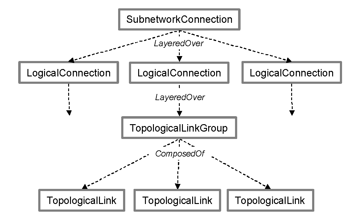
The end-to-end client service across a subnetwork is represented by a SubnetworkConnection that is ConnectedTo CTP objects on the client ports (not shown in Connection Object Classes and Their Relationships ). Generally, a path through a network is represented by a number of LogicalConnection objects, each LogicalConnection representing a connection across a segment of the network that provides protection capability such as 1+1 or 2F-BLSR.
The TopologicalLinkGroup objects are ComposedOf TopologicalLink objects that represent the physical connections that comprise the protection group. In addition, RingProtectionGroup objects and/or LogicalConnectionProtectionTPGroup objects model physical topology such as BLSR/MS-SPRing or UPSR/SNCP rings. “Protection Schemes” on page 95 provides more details.
The Optical Transport Manager represents logical connections across a protection ring using LogicalConnection objects LayeredOver TopologicalLinkGroup objects. The Optical Transport Manager uses additional relationships and objects that are specific to each LogicalConnection object to calculate root causes and impacts. “Notifications and Impacts for SONET/SDH Networks” on page 69 and “Notifications and Impacts for WDM Networks” on page 83 provide more information.
