


The physical fiber links between network elements are modeled using two types of topological link, depending on whether the Optical Transport Manager manages the network element on one or both ends of the link.
-
DropSideTopologicalLink is used to model links where the Optical Transport Manager manages only one end of the link.
-
TopologicalLink is used to model links where the Optical Transport Manager manages both ends of the link.
TopologicalLink and DropSideTopologicalLink objects and relationships shows the connection between devices and fiber links, which is modeled using a ConnectedTo relationship between a TopologicalLink and the appropriate PTP object in the network element at each end of the link.
Figure 1. TopologicalLink and DropSideTopologicalLink objects and relationships 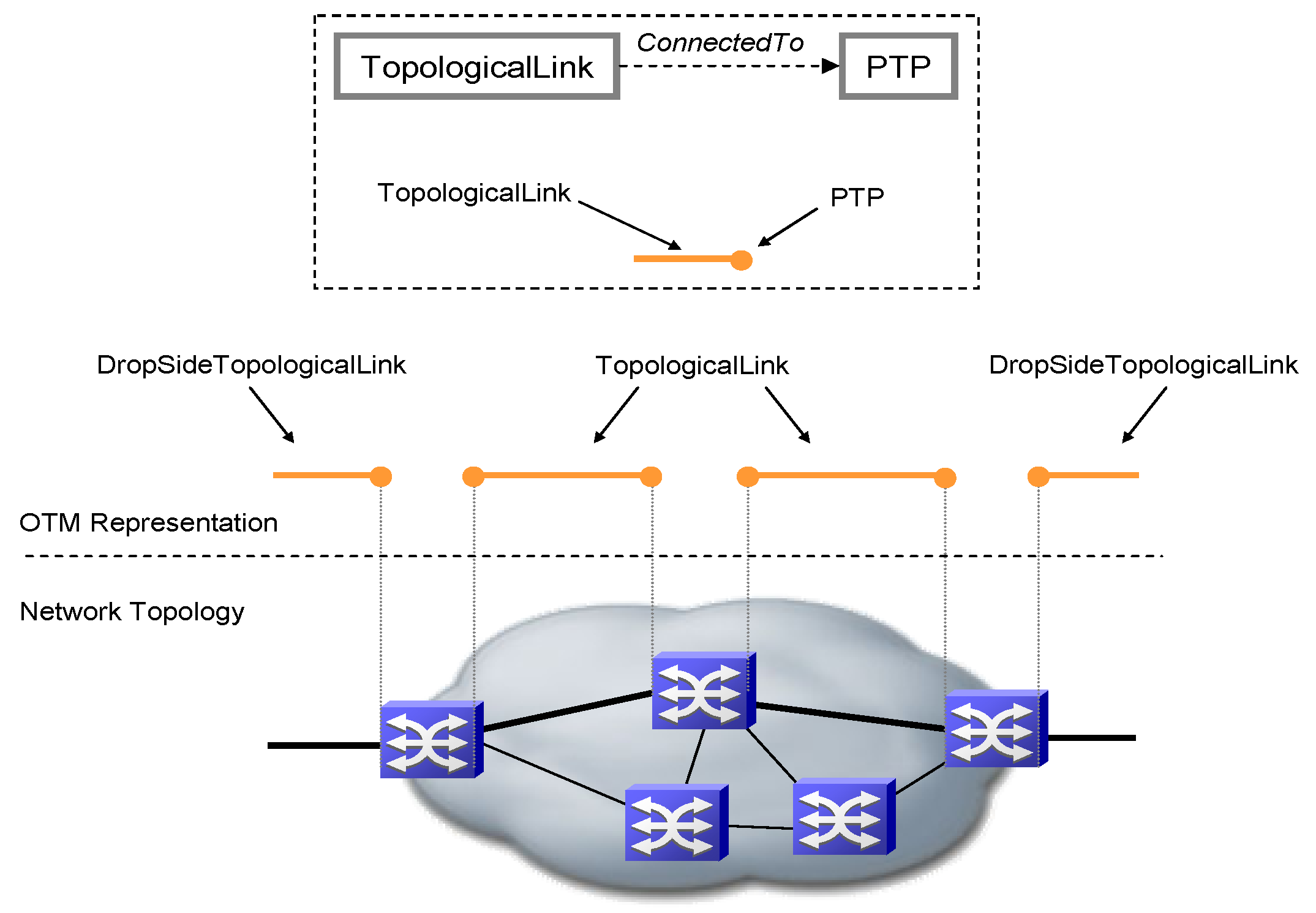
The root-cause and impact analysis calculations are slightly different in each of the classes representing topological links. These calculations take account of the fact that some alarms are not received when problems happen on drop-side connections.
Note:The TopologicalLink class can be used in the VMware Smart Assurance model to represent uni-directional or bi-directional connections, as appropriate. In the SONET/SDH model, these objects represent a bi-directional connection. For example, each TopologicalLink object represents a fiber pair.
