


This topic describes how to isolate tenants in VMware Tanzu Kubernetes Grid Integrated Edition (TKGI) multi-tenant environments.
About Tenant Isolation
You can isolate a cluster and its workloads using NSX Tier-0 (T0) logical routers or VRF Tier-0 gateways:
- Using a Multi-T0 Router Configuration for Tenant Isolation
- Using a VRF Tier-0 Gateway Configuration for Tenant Isolation
Using a Multi-T0 Router Configuration for Tenant Isolation
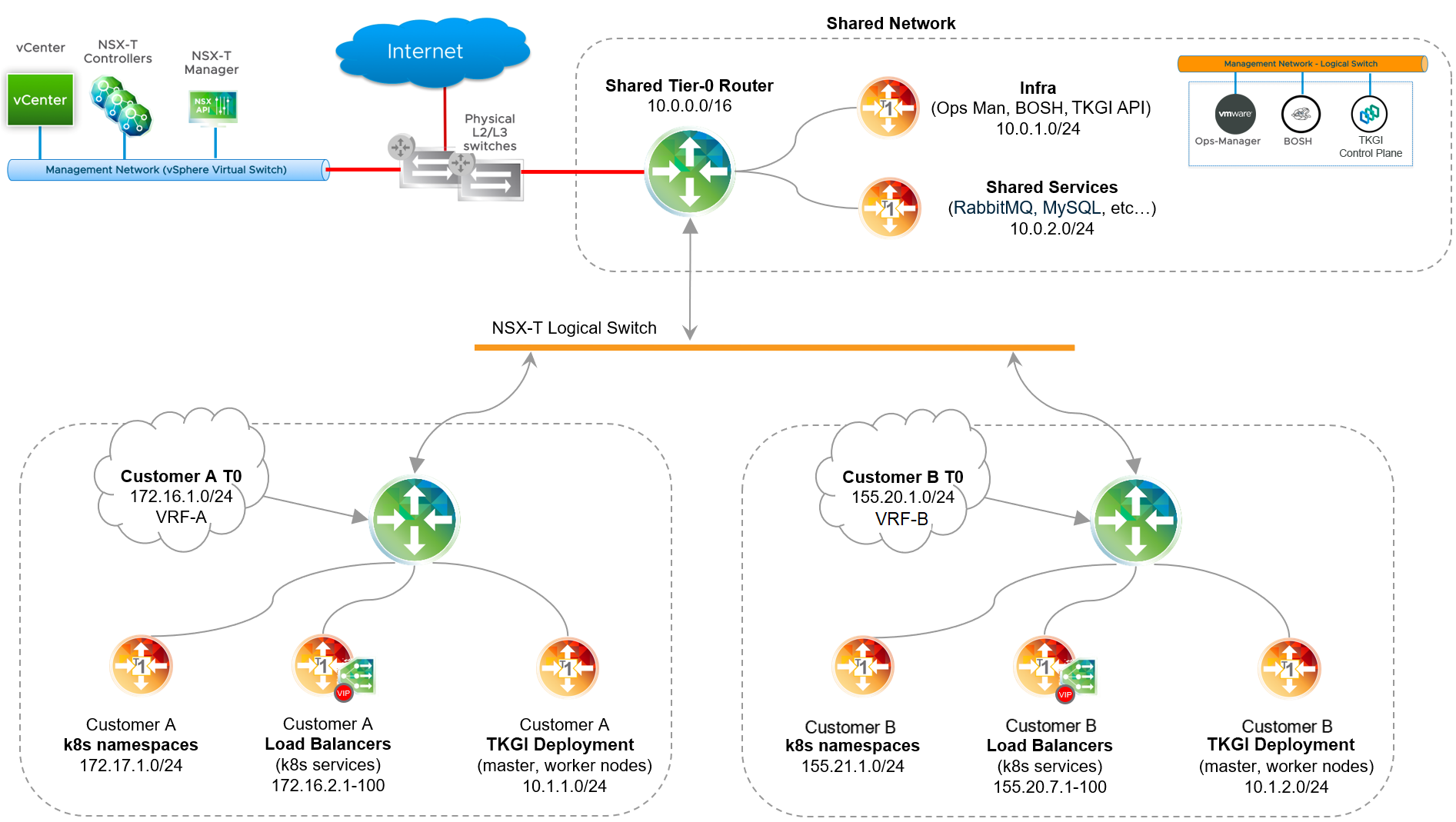
Tanzu Kubernetes Grid Integrated Edition multi-T0 lets you provision, manage, and secure Kubernetes cluster deployments on isolated tenant networks. As shown in the diagram below, instead of having a single T0 router, there are multiple T0 routers. The Shared Tier-0 router handles traffic between the TKGI management network and the vSphere standard network where vCenter and NSX Manager are deployed. There are two Tenant Tier-0 routers that connect to the Shared Tier-0 over an NSX logical switch using a virtual LAN (VLAN) or Overlay transport zone. Using each dedicated T0, Kubernetes clusters are deployed in complete isolation on each tenant network.
To isolate a cluster and its workloads behind T0 routers:
Using a VRF Tier-0 Gateway Configuration for Tenant Isolation
Tanzu Kubernetes Grid Integrated Edition on vSphere with NSX Policy API also supports provisioning, managing, and securing Kubernetes cluster deployments using a VRF gateway.
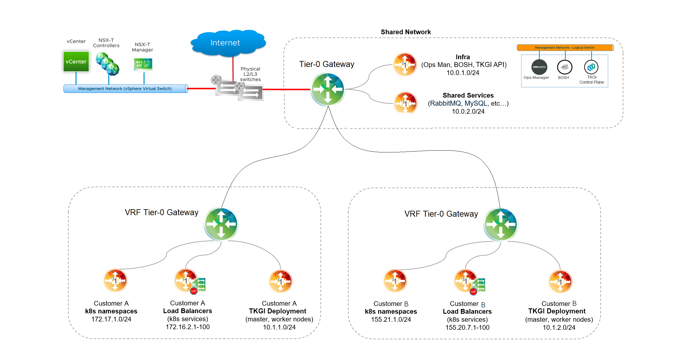
As shown in the diagram below, instead of using one or more T0 routers, clusters are isolated behind a VRF gateway. The Shared Tier-0 router handles traffic between the TKGI management network and the vSphere standard network where vCenter and NSX Manager are deployed. Using Tenant VRF Tier-0 gateways to connect to the Shared Tier-0, Kubernetes clusters are deployed in complete isolation on tenant networks.
To isolate a cluster and its workloads behind a VRF gateway:
Prerequisites
The prerequisites for tenant isolation depend on the configuration used:
- Multi-T0-Based Tenant Isolation Prerequisites
- VRF Tier-0 Gateway-Based Tenant Isolation Prerequisites
Multi-T0-Based Tenant Isolation Prerequisites
To implement Multi-T0-based tenant isolation, verify the following prerequisites:
- Supported version of vSphere IaaS is installed. See vSphere with NSX Version Requirements.
- Supported version of VMware NSX is installed. See vSphere with NSX Version Requirements.
- If you are using NAT mode for the Shared Tier-0 router, review Considerations for NAT Topology on Shared Tier-0 and Considerations for NAT Topology on Tenant Tier-0 before proceeding.
VRF Tier-0 Gateway-Based Tenant Isolation Prerequisites
To implement VRF Tier-0 Gateway-based tenant isolation:
- TKGI on vSphere with NSX Policy API.
- Three VLANs for the VRF Tier-0 gateway.
Configure Multi-T0 Router-Based Tenant Isolation
To isolate tenants using a multi-T0 router-based configuration:
- Plan and Provision Additional NSX Edge Nodes for Each Multi-T0 Router
- Configure Inter-T0 Logical Switch
- Configure a New Uplink Interface on the Shared Tier-0 Router
- Provision Tier-0 Router for Each Tenant
- Create Two Uplink Interfaces on Each Tenant Tier-0 Router
- Verify the Status of the Shared and Tenant Tier-0 Routers
- Configure Static Routes
- Considerations for NAT Topology on Shared Tier-0
- Considerations for NAT Topology on Tenant Tier-0
- Configure BGP on Each Tenant Tier-0 Router
- Configure BGP on the Shared Tier-0 Router
- Test the Base Configuration
Step 1: Plan and Provision Additional NSX Edge Nodes for Each Multi-T0 Router
Multi-T0 requires a minimum of four NSX Edge Nodes: Configure two nodes per T0. Use the T0 attached to the TKGI management plane as the Shared Tier-0 router that connects all T0 routers. In addition, deploy an additional T0 router for each tenant you want to isolate.
Each Tenant Tier-0 router requires a minimum of two NSX Edge Nodes. The formula for determining the minimum number of nodes for all tenants is as follows:
2 + (TENANTS x 2)
Where TENANTS is the number of tenants you want to isolate.
For example, if you want to isolate three tenants, use the following calculation:
2 + (3 x 2) = 8 NSX Edge Nodes
To isolate ten tenants, use the following calculation:
2 + (10 x 2) = 22 NSX Edge Nodes
Using the NSX Manager interface, deploy at least the minimum number of Edge Nodes you need for each Tenant Tier-0 and join these Edge Nodes to an Edge Cluster. For more information, see Installing and Configuring NSX-T Data Center v3.0 for TKGI.
Note: An Edge Cluster can have a maximum of 10 Edge Nodes. If the provisioning requires more Edge Nodes than what a single Edge Cluster can support, multiple Edge Clusters must be deployed.
Step 2: Configure Inter-T0 Logical Switch
Connect all NSX Edge Nodes using an overlay logical switch. This overlay network is used to transport traffic between the T0 routers. Plan to allocate a network of sufficient size to accommodate all Tier-0 router interfaces that need to be connected to this network. You must allocate each T0 router one or more IP addresses from that range.
For example, if you plan to deploy two Tenant Tier-0 routers, a subnet with prefix size /28 might be sufficient, such as 50.0.0.0/28.
Once you have physically connected the Edge Nodes, define a logical switch to connect the Shared Tier-0 router to the Tenant Tier-0 router or routers.
To define a logical switch based on an Overlay or VLAN transport zone, follow the steps below:
- In NSX Manager, go to Networking > Switching > Switches.
- Click Add and create a logical switch (LS).
- Name the switch descriptively, such as
inter-t0-logical-switch. - Connect the logical switch to the transport zone defined when deploying NSX. See Installing and Configuring NSX-T Data Center v3.0 for TKGI.
Step 3: Configure a New Uplink Interface on the Shared Tier-0 Router
The Shared Tier-0 router already has an uplink interface to the external (physical) network that was configured when it was created. For more information, see Installing and Configuring NSX-T Data Center v3.0 for TKGI.
To enable Multi-T0, you must configure a second uplink interface on the Shared Tier-0 router that connects to the inter-T0 network (inter-t0-logical-switch, for example). To do this, complete the following steps:
- In NSX Manager, go to Networking > Routers.
- Select the Shared Tier-0 router.
- Select Configuration > Router Ports and click Add.
- Configure the router port as follows:
- For the logical switch, select the inter-T0 logical switch you created in the previous step (for example,
inter-t0-logical-switch). - Provide an IP address from the allocated range. For example,
50.0.0.1/24.
- For the logical switch, select the inter-T0 logical switch you created in the previous step (for example,
Step 4: Provision Tier-0 Router for Each Tenant
Create a Tier-0 logical router for each tenant you want to isolate. For more information, see Create Tier-0 Router in Installing and Configuring NSX-T Data Center v3.0 for TKGI.
When creating each Tenant Tier-0 router, make sure you set the router to be active/passive, and be sure to name the logical switch descriptively, such as t0-router-customer-A.
Step 5: Create Two Uplink Interfaces on Each Tenant Tier-0 Router
Similar to the Shared Tier-0 router, each Tenant Tier-0 router requires at a minimum two uplink interfaces.
-
The first uplink interface provides an uplink connection from the Tenant Tier-0 router to the tenant’s corporate network.
-
The second uplink interface provides an uplink connection to the Inter-T0 logical switch that you configured. For example,
inter-t0-logical-switch.
For instructions, see Create Tier-0 Router in Installing and Configuring NSX-T Data Center v3.0 for TKGI. When creating the uplink interface that provides an uplink connection to the Inter-T0 logical switch, be sure to give this uplink interface an IP address from the allocated pool of IP addresses.
Step 6: Verify the Status of the Shared and Tenant Tier-0 Routers
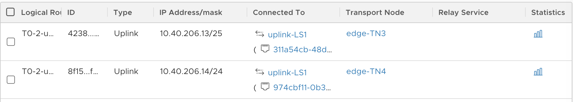
When you have completed the configuration of the Shared and Tenant Tier-0 routers as described above, verify your progress up to this point. On the Shared Tier-0 router, confirm you have two uplink interfaces, one to the external network and the other to the inter-T0 logical switch. On the Tenant Tier-0 router, confirm you have two uplink interfaces, one to the inter-T0 logical switch and the other to the external network. Each uplink interface is connected to a transport node.
The images below provide an example checkpoint for verifying the uplink interfaces for the Shared and Tenant Tier-0 routers. In this example, the Shared Tier-0 has one uplink interface at 10.40.206.10/25 on the transport Edge Node edge-TN1, and the second uplink interface at 10.40.206.9/25 on the transport Edge Node edge-TN2.
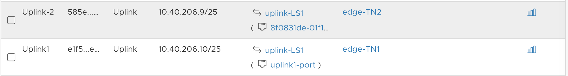
Similarly, the Tenant Tier-0 has one uplink interface at 10.40.206.13/25 on the transport Edge Node edge-TN3, and the second uplink interface at 10.40.206.14/25 on the transport Edge Node edge-TN4.
Step 7: Configure Static Routes
To configure static routes:
-
For each T0 router, including the Shared Tier-0 and all Tenant Tier-0 routers, define a static route to the external network. For instructions, see Create Tier-0 Router in Installing and Configuring NSX-T Data Center v3.0 for TKGI.
-
For the Shared Tier-0 router, the default static route points to the external management components such as vCenter and NSX Manager and provides internet connectivity.
As shown in the image below, the Shared Tier-0 defines a static route for vCenter and NSX Manager as
192.168.201.0/24, and the static route for internet connectivity as0.0.0.0/0: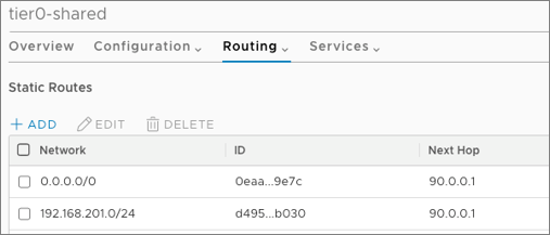
-
Confirm that the default static route for each Tenant Tier-0 router points to the tenant’s corporate network.
As shown in the image below, the Tenant Tier-0 defines a static route to the corporate network as
0.0.0.0/0: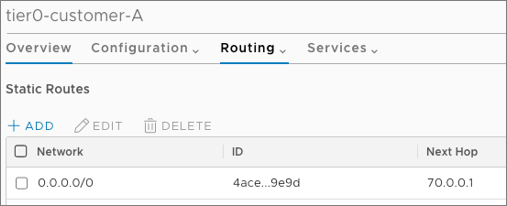
Step 8: Considerations for NAT Topology on Shared Tier-0
The Multi-T0 configuration steps documented here apply to deployments where NAT mode is not used on the Shared Tier-0 router. For more information, see NSX Deployment Topologies for Tanzu Kubernetes Grid Integrated Edition.
For deployments where NAT-mode is used on the Shared Tier-0 router, additional provisioning steps must be followed to preserve NAT functionality to external networks while bypassing NAT rules for traffic flowing from the Shared Tier-0 router to each Tenant Tier-0 router.
Existing Tanzu Kubernetes Grid Integrated Edition deployments where NAT mode is configured on the Shared Tier-0 router cannot be re-purposed to support a Multi-T0 deployment following this documentation.
Step 9: Considerations for NAT Topology on Tenant Tier-0
Note: This step only applies to NAT topologies on the Tenant Tier-0 router. For more information on NAT mode, see NSX Deployment Topologies for TKGI.
Note: NAT mode for Tenant Tier-0 routers is enabled by defining a non-routable custom Pods IP Block using a Network Profile. For more information, see Defining Network Profiles.
In a Multi-T0 environment with NAT mode, traffic on the Tenant Tier-0 network going from Kubernetes cluster nodes to TKGI management components residing on the Shared Tier-0 router must bypass NAT rules. This is required because TKGI-managed components such as BOSH Director connect to Kubernetes nodes based on routable connectivity without NAT.
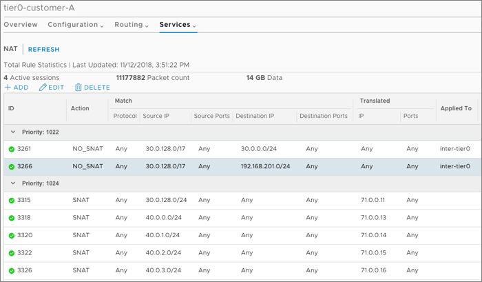
To avoid NAT rules being applied to this class of traffic, you need to create two high-priority NO_SNAT rules on each Tenant Tier-0 router. These NO_SNAT rules allow “selective” bypass of NAT for the relevant class of traffic, which in this case is connectivity from Kubernetes node networks to TKGI management components such as the TKGI API, Ops Manager, and BOSH Director, as well as to infrastructure components such as vCenter and NSX Manager.
For each Tenant Tier-0 router, define two NO_SNAT rules to classify traffic. The source for both rules is the Nodes IP Block CIDR. The destination for one rule is the TKGI Management network where TKGI, Ops Manager, and BOSH Director are deployed. The destination for the other rule is the external network where NSX Manager and vCenter are deployed.
For example, the following image shows two NO_SNAT rules created on a Tenant Tier-0 router. The first rule un-NATs traffic from Kubernetes nodes (30.0.128.0/17) to the TKGI management network (30.0.0.0/24). The second rule un-NATs traffic from Kubernetes nodes (30.0.128.0/17) to the external network (192.168.201.0/24).
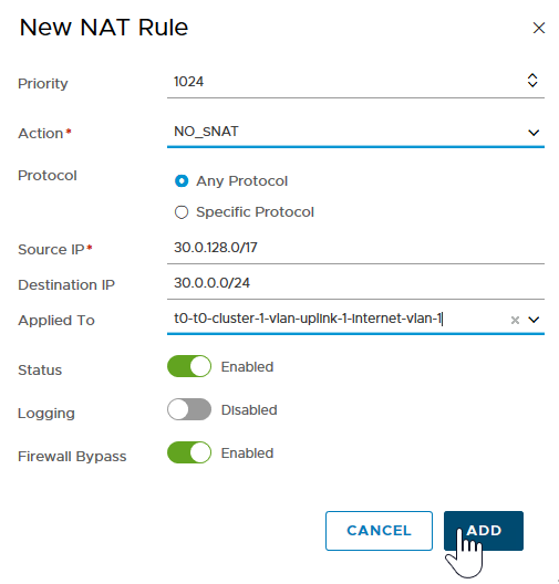
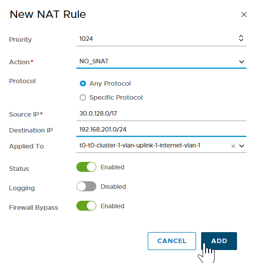
The end result is two NO_SNAT rules on each Tenant Tier-0 router that bypass the NAT rules for the specified traffic.
Step 10: Configure BGP on Each Tenant Tier-0 Router
Use Border Gateway Protocol (BGP) to route redistribution and filtering across all Tier-0 routers. BGP allows the Shared Tier-0 router to dynamically discover the location of Kubernetes clusters (Node networks) deployed on each Tenant Tier-0 router.
To configure BGP on each tenant Tier-0 router:
- Considerations When Configuring BGP on Tenant Tier-0 Routers
- Configure BGP AS Number
- Configure BGP Route Distribution
- Configure IP Prefix Lists
- Configure BGP Peer
Considerations When Configuring BGP on Tenant Tier-0 Routers
In a Multi-T0 deployment, special consideration must be given to the network design to preserve reliability and fault tolerance of the Shared and Tenant Tier-0 routers.
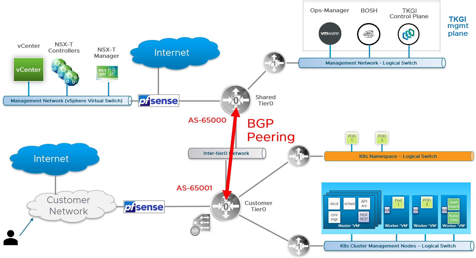
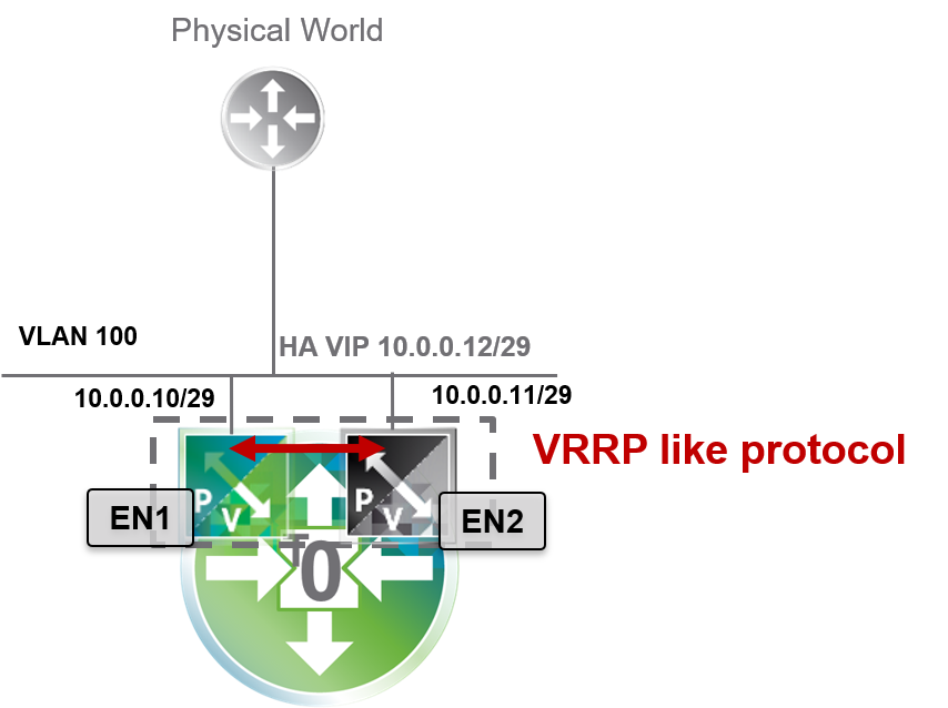
Failover of a logical router is triggered when the router is losing all of its BGP sessions. If multiple BGP sessions are established across different uplink interfaces of a Tier-0 router, failover will only occur if all such sessions are lost. Thus, to ensure high availability on the Shared and Tenant Tier-0 routers, BGP can only be configured on uplink interfaces facing the Inter-Tier-0 network. This configuration is shown in the diagram below.
Note: In a Multi-T0 deployment, BGP cannot be configured on external uplink interfaces. Uplink external connectivity must use VIP-HA with NSX to provide high availability for external interfaces. For more information, see Deploy NSX Edge Nodes in Installing and Configuring NSX-T Data Center v3.0 for TKGI.
You must configure BGP routing on each Tier-0 router. The steps that follow are for each Tenant Tier-0 router. The instructions for the Shared Tier-0 are provided in subsequent steps. As a prerequisite, assign a unique Autonomous System Number to each Tier-0 router. Each AS number you assign must be private within the range 64512-65534. For more information, see Configure BGP on a Tier-0 Logical Router in the NSX documentation.
Note: To configure BGP for the Tenant Tier-0, you will need to use the Shared Tier-0 AS number. As such, identify the AS numbers you will use for the Tenant and Shared Tier-0 routers before proceeding.
Configure BGP AS Number
Once you have chosen the AS number for the Tenant Tier-0 router, configure BGP with the chosen AS number as follows:
- In NSX Manager, select Networking > Routers.
- Select the Tenant Tier-0 router.
- Select Routing > BGP, the click ADD.
- Add the AS number to the BGP configuration in the
local ASfield. - Click the
enabledslider to activate BGP. - Lastly, deactivate the ECMP slider.
Configure BGP Route Distribution
To configure BGP route distribution for each Tenant Tier-0 router, follow the steps below:
- In NSX Manager, select the Tenant Tier-0 router.
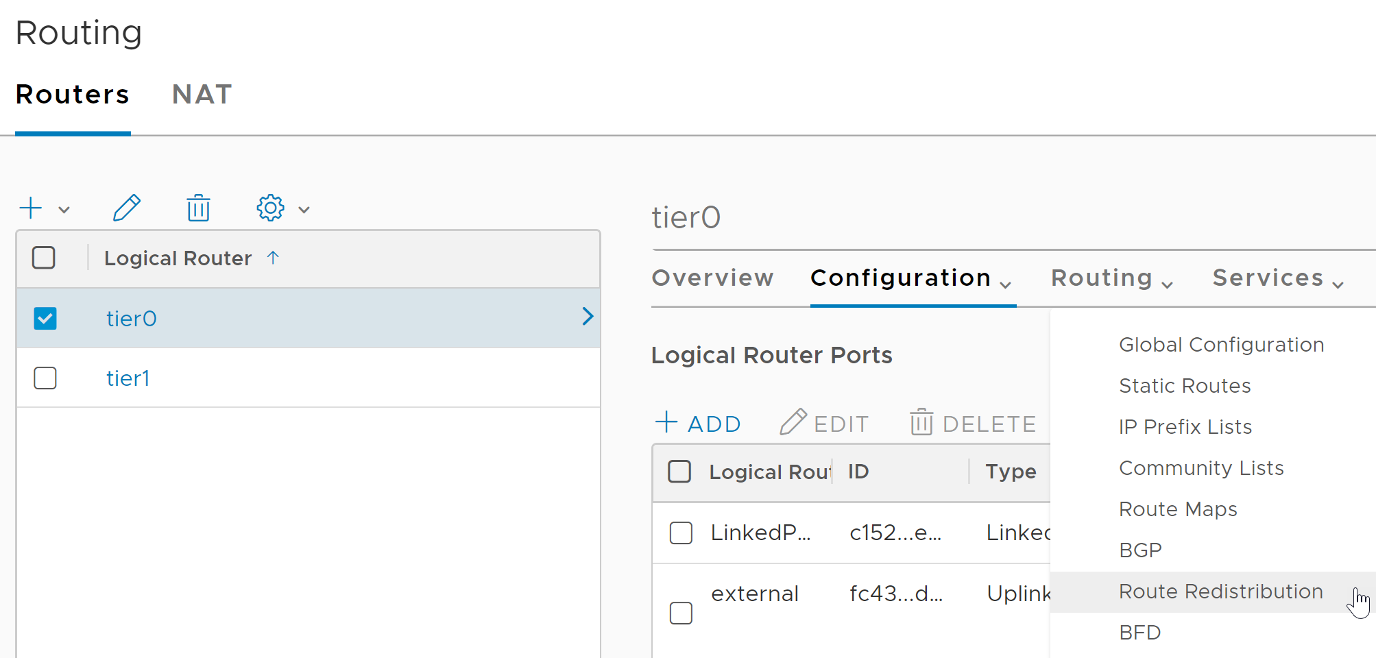
- Select Routing > Route Redistribution.
- Click Add and configure as follows:
- Name: NSX Static Route Redistribution
- Sources: Select Static, NSX Static, and NSX Connected
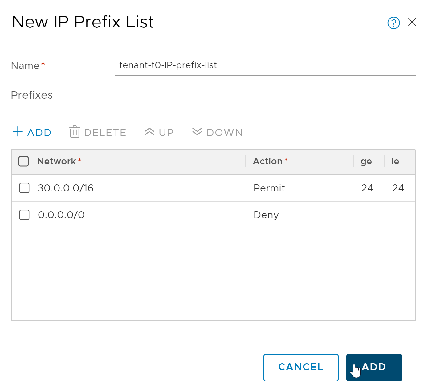
Configure IP Prefix Lists
In this step you define an IP Prefix List for each Tenant Tier-0 router to advertise any Kubernetes node network of standard prefix size /24, as specified by the less-than-or-equal-to (le) and greater-than-or-equal-to (ge) modifiers in the configuration. The CIDR range to use for the definition of the list entry is represented by the Nodes IP Block network, for example 30.0.0.0/16.
For more information about IP Prefix Lists, see Create an IP Prefix List in the NSX documentation.
To configure an IP Prefix List for each Tenant Tier-0 router, follow the steps below:
- In NSX Manager, select the Tenant Tier-0 router.
- Select Routing > IP Prefix Lists.
- Click Add and configure as follows:
- Name: Enter a descriptive name.
- Click Add and create a Permit rule that allows redistribution of the exact /24 network, carved from the Nodes IP Block.
- Click Add and create a Deny rule that denies everything else on the network
0.0.0.0/0.
Configure BGP Peer
To configure BGP peering for each Tenant Tier-0 router, follow the steps below:
- In NSX Manager, select the Tenant Tier-0 router.
- Go to Routing > BGP.
- Click Add and configure the BGP rule as follows:
- Neighbor Address: Enter the IP address of the Shared Tier-0 router.
- Local Address: Select the individual uplink interfaces facing the inter-tier0 logical switch.
- Address Families: Click Add and configure as follows:
- Type:
IPV4_UNICAST. - State:
Enabled. - Out Filter: Select the IP Prefix List created above.
- Click Add.
- Type:
- Back at the Routing > BGP screen:
- Enter the Shared Tier-0 AS number.
- After creating the BGP neighbor, select Edit and click Enable BGP.
Step 11: Configure BGP on the Shared Tier-0 Router
The configuration of BGP on the Shared Tier-0 is similar to the BGP configuration each Tenant Tier-0, with the exception of the IP Prefix list that permits traffic to the TKGI management network where TKGI, BOSH, and Ops Manager are located.
As with each Tenant Tier-0 router, you will need to assign a unique private AS number within the private range 64512-65534 to the Shared Tier-0 router. Once the AS number is assigned, use NSX Manager to configure the following BGP rules for the Shared Tier-0 router.
Configure BGP AS Number
To configure BGP on the Shared Tier-0 with the AS number, complete the corresponding set of instructions in the tenant BGP section above.
Configure BGP Route Distribution
To configure BGP route distribution for the Shared Tier-0 router, complete the corresponding set of instructions in the BGP tenant section above.
Configure IP Prefix Lists
To configure IP prefix lists for each Tenant Tier-0 router, follow the steps below:
- In NSX Manager, select the Tenant Tier-0 router.
- Select Routing > IP Prefix Lists.
- Click Add and configure as follows:
- Name: Enter a descriptive name.
- Click Add and create a Permit rule for the infrastructure components vCenter and NSX Manager.
- Click Add and create a Permit rule for the TKGI management components (TKGI, Ops Manager, and BOSH).
- Click Add and create a Deny rule that denies everything else on the network
0.0.0.0/0.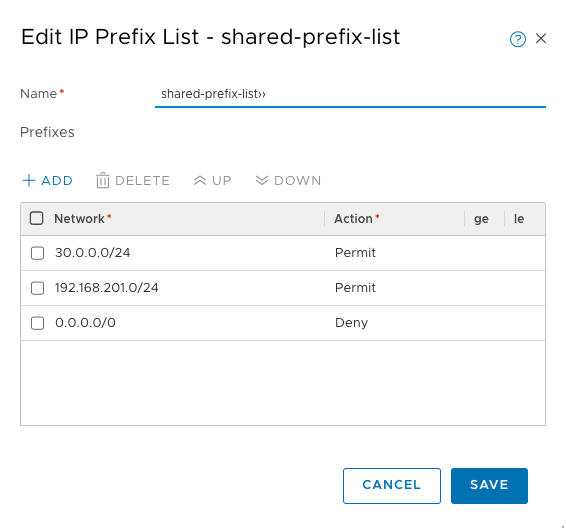
Configure BGP Peer
- In NSX Manager, select the Tenant Tier-0 router.
- Go to Routing > BGP.
- Click Add and configure the BGP rule as follows:
- Neighbor Address: Enter the IP address of the Shared Tier-0 router.
- Local Address: Select All Uplinks.
- Address Families: Click Add and configure as follows:
- Type: IPV4_UNICAST
- State: Enabled
- Out Filter: Select the IP Prefix List that includes the network where vCenter and NSX Manager are deployed, as well as the network where the TKGI management plane is deployed.
- Click Add.
- Back at the Routing > BGP screen:
- Enter the Tenant Tier-0 AS number.
- After creating the BGP neighbor, select Edit and click Enable BGP.
Note: You must repeat this step for each Tenant Tier-0 router you want to peer with the Shared Tier-0 router.
Step 12: Test the Base Configuration
Perform the following validation checks on all Tier-0 routers:
Perform the validation checks on the Shared Tier-0 first followed by each Tenant Tier-0 router. For each Tier-0, confirm the validation alternates among checking for the BGP summary and the router Routing Table.
Shared Tier-0 Validation
Verify that the Shared Tier-0 has an active peer connection to each Tenant Tier-0 router.
To verify BGP Peering:
- In NSX Manager, select the Shared Tier-0 router and choose Actions > Generate BGP Summary.
- Validate that the Shared Tier-0 router has one active peer connection to each Tenant Tier-0 router.
Verify that the Shared Tier-0 routing table includes all BGP routes to each Shared Tier-0:
- In NSX Manager, select Networking > Routers > Routing.
- Select the Shared Tier-0 router and choose Actions > Download Routing Table.
- Download the routing table for the Shared Tier-0 and verify the routes.
Tenant Tier-0 Validation
Verify that the Shared Tier-0 has an active peer connection to each Tenant Tier-0 router.
To verify BGP Peering:
- In NSX Manager, select the Tenant Tier-0 router and choose Actions > Generate BGP Summary.
- Validate that the Tenant Tier-0 router has one active peer connection to the Shared Tier-0 router.
- Repeat for all other Tenant Tier-0 routers.
Verify that the T0 routing table for each Tenant Tier-0 includes all BGP routes to reach vCenter, NSX Manager, and the TKGI management network:
- In NSX Manager, select Networking > Routers > Routing.
- Select the T0 router and choose Actions > Download Routing Table.
- Download the routing table for each of the Tenant Tier-0 routers.
Note: At this point, the Shared Tier-0 has no BGP routes because you have not deployed any Kubernetes clusters. The Shared Tier-0 will show BGP routes when you deploy Kubernetes clusters to the Tenant Tier-0 routers. Each Tenant Tier-0 router shows a BGP exported route that makes each Tenant Tier-0 router aware of the TKGI management network and other external networks where NSX and vCenter are deployed.
Configure Multi-T0 Security
In a multi-T0 environment, you can secure two types of traffic:
- Traffic between tenants. See Secure Inter-Tenant Communications.
- Traffic between clusters in the same tenant. See Secure Intra-Tenant Communications.
Secure Inter-Tenant Communications
Securing traffic between tenants isolates each tenant and ensures the traffic between the Tenant Tier-0 routers and the Shared Tier-0 router is restricted to the legitimate traffic path.
To secure traffic between tenants:
Step 1: Define IP Sets
In NSX an IP Set is a group of IP addresses that you can use as sources and destinations in firewall rules. For a Multi-T0 deployment you need to create several IP Sets as described below. For more information about creating IP Sets, see Create an IP Set in the NSX documentation.
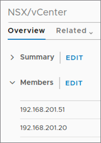
The image below shows a summary of the three required IP Sets you will need to create for securing Multi-T0 deployments:
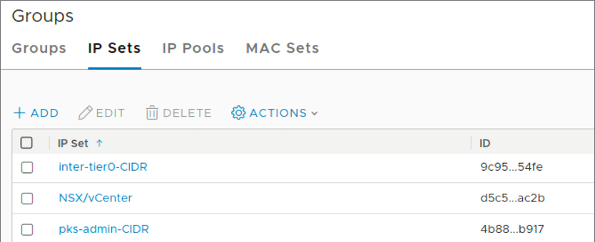
First, define an IP Set that includes the IP addresses for the NSX Manager and vCenter hosts. In the following IP Set example, 192.168.201.51 is the IP address for NSX and 192.168.201.20 is the IP address for vCenter.
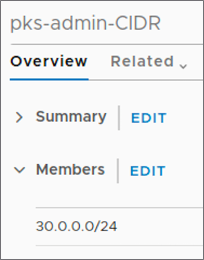
Next, define an IP Set that includes the network CIDR for TKGI management components. In the following IP Set example, 30.0.0.0/24 is the CIDR block for the TKGI Management network.
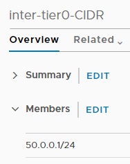
Lastly, define an IP Set for the Inter-T0 CIDR created during the base configuration.
Note: These are the minimum IP Sets you need to create. You might want to define additional IP Sets for convenience.
Step 2: Create Edge Firewall
VMware NSX uses Edge Firewall sections and rules to specify traffic handling in and out of the network. A firewall section is a collection of firewall rules. For more information, see About Firewall Rules in the NSX documentation.
For each Tenant Tier-0 router, create an Edge Firewall and section as follows:
- In NSX Manager, go to Networking > Routers.
- Select the Tenant Tier-0 router and click Services > Edge Firewall.
- Select the Default LR Layer 3 Section.
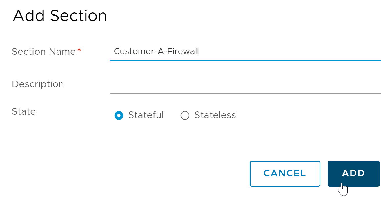
- Click Add Section > Add Section Above.
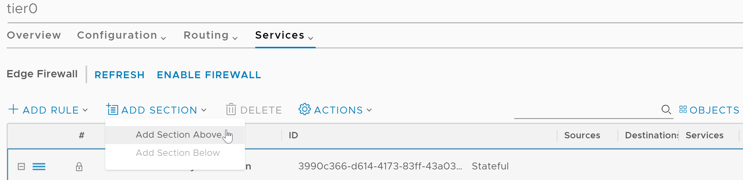
- Configure the section as follows:
- Section Name: Enter a unique name for the firewall section.
- State: Stateful
Step 3: Add Firewall Rules
The last step is to define several firewall rules for the Edge Firewall. The firewall rules allow only legitimate control plane traffic to traverse the inter-Tier-0 logical switch, and deny all other traffic.
The following image shows a summary of the five firewall rules you will create: 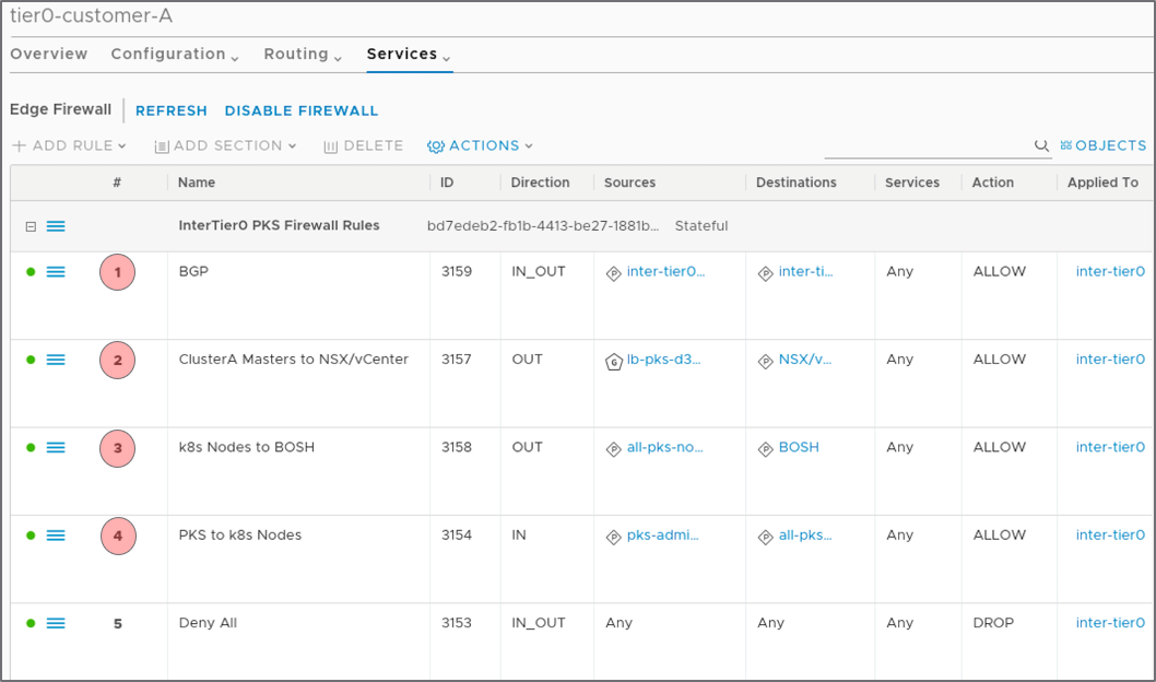
Note: All firewall rules are applied to the Inter-T0-Uplink interface.
Select the Edge Firewall Section you just created, then select Add Rule. Add the following five firewall rules:
- BGP Firewall Rule
- Clusters Masters Firewall Rule
- Node Network to Management Firewall Rule
- TKGI Firewall Rule
- Deny All Firewall Rule
BGP Firewall Rule
- Name:
BGP - Direction: in and out
- Source: IP Set defined for the Inter-T0 CIDR
- Destination: IP Set for Inter-T0 CIDR
- Service: Any
- Action: Allow
- Apply the rule to the Inter-T0-Uplink interface.
- Save the firewall rule.
Clusters Masters Firewall Rule
The source for this firewall rule is a Namespace Group (NSGroup) you define in NSX Manager. The NSGroup is the Bootstrap Security Group specified in the Network Profile associated with this tenant. See Bootstrap Security Group (NSGroup).
Once you have defined the NSGroup, configure the firewall rule as follows.
- Name:
Clusters-Masters-to-NSX-and-VC - Direction: out
- Source: NSGroup for Kubernetes Control Plane Nodes
- Destination: IP Set for Inter-T0 CIDR
- Service: Any
- Action: Allow
- Apply the rule to the Inter-T0-Uplink interface.
- Save the firewall rule.
Node Network to Management Firewall Rule
This firewall rule allows Kubernetes node traffic to reach TKGI management VMs and the standard network.
- Name:
Node-Network-to-Management - Direction: out
- Source: IP Set defined for the Nodes IP Block network
- Destination: IP Sets defined for vCenter, NSX Manager, and TKGI management plane components
- Service: Any
- Action: Allow
- Apply the rule to the Inter-T0-Uplink interface.
- Save the firewall rule.
TKGI Firewall Rule
This firewall rule allows TKGI management plane components to talk to Kubernetes nodes.
- Name:
TKGI-to-Node-Network - Direction: ingress
- Source: IP Set defined for the TKGI management network
- Destination: IP Set defined for the Nodes IP Block network
- Service: Any
- Action: Allow
- Apply the rule to the Inter-T0-Uplink interface.
- Save the firewall rule.
Deny All Firewall Rule
- Name:
Deny All. This setting drops all other traffic that does not meet the criteria of the first three rules. - Direction: in and out
- Source: Any
- Destination: Any
- Service: Any
- Action: Drop
- Apply the rule to the Inter-T0-Uplink interface.
- Save the firewall rule.
(Optional) Step 4: Create DFW Section
To use distributed firewall (DFW) rules, you must create a DFW section for the DFW rule set. The DFW section must exist before you create a Kubernetes cluster.
This optional step is recommended for inter-tenant security. It is required for intra-tenant security as described in Secure Intra-Tenant Communications. Because you need to create the DFW section only once, you can use the DFW section you configure in this step when defining DFW rules for intra-tenant communications.
Even if you do not currently plan to use DFW rules, you can create the DFW section and use it later if you decide to define DFW rules. Those rules will apply to any cluster created after you define the DFW section for the tenant Tier-0 router.
Note: You must perform this procedure before you deploy a Kubernetes cluster to the target tenant Tier-0 router.
- In NSX Manager, navigate to Security > DFW, select the top-most rule, and click Add Section Above.
- Configure the section as follows:
- In the Section Name field, enter a name for your DFW section. For example,
tkgi-dfw. - Use the defaults for all other settings on the New Section page.
- Navigate to the Manage Tags page and add a new tag.
- In the Tag field, enter
top. - In the Scope field, enter
ncp/fw_sect_marker.
- In the Tag field, enter
- In the Section Name field, enter a name for your DFW section. For example,
Secure Intra-Tenant Communications
To secure communication between clusters in the same tenancy, you must disallow any form of communication between Kubernetes clusters created by TKGI. Securing inter-cluster communications is achieved by provisioning security groups and DFW rules.
Note: You must perform the global procedures, the first three steps described below, before you deploy a Kubernetes cluster to the target tenant Tier-0 router.
To secure communication between clusters in the same tenancy:
- Create NSGroup for All Tanzu Kubernetes Grid Integrated Edition Clusters
- Create DFW Section
- Create NSGroups
- Create DFW Rules
Step 1: Create NSGroup for All Tanzu Kubernetes Grid Integrated Edition Clusters
- In NSX Manager, navigate to Inventory > Groups > Groups and Add new group.
- Configure the new NSGroup as follows:
- In the Name field, enter
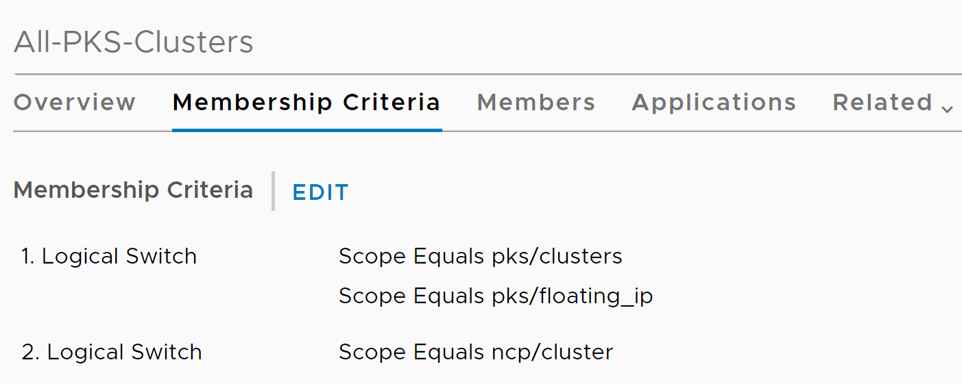
All-TKGI-Clusters. - In the Membership Criteria tab, add the following two criteria:
- For the first criterion, select Logical switch.
- For Scope > Equals, enter
pks/clusters. - For Scope > Equals, enter
pks/floating_ip. - For the second criterion, select Logical switch.
- For Scope > Equals, enter
ncp/cluster.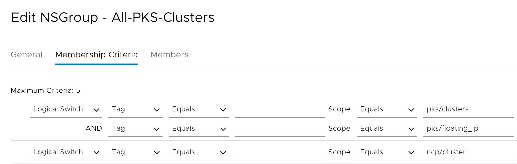
- In the Name field, enter
Note: The pks/clusters, pks/floating_ip, or ncp/cluster values are the exact values you must enter when configuring Scope > Equals. They map to NSX objects.
After you configure the All-TKGI-Clusters NSGroup, the Membership Criteria tab looks as follows:
Step 2: Create DFW Section
Before you create distributed firewall rules, you must create a DFW section for the DFW rule set you define later.
To create a DFW section, follow the instructions in Create DFW Section.
Step 3: Create NSGroups
Before creating NSGroups, retrieve the UUID of the cluster that you want to secure. To retrieve the cluster UUID, run the tkgi cluster YOUR-CLUSTER-NAME command. For more information about the TKGI CLI, see TKGI CLI.
Create NSGroup for Cluster Nodes
- In NSX Manager, navigate to Inventory > Groups > Groups and click Add new group.
- Configure the new NSGroup as follows:
- In the Name field, enter the cluster UUID or cluster name and append
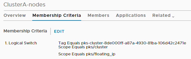
-nodesto the end of the name to distinguish it. The cluster name must be unique. - In the Membership Criteria tab, add the following criterion:
- Select Logical Switch.
- For Tag > Equals, enter
tkgi-cluster-YOUR-CLUSTER-UUID. - For Scope > Equals, enter
pks/cluster. - For Scope > Equals, enter
pks/floating_ip. For this scope, leave the Tag field empty as shown in the image below.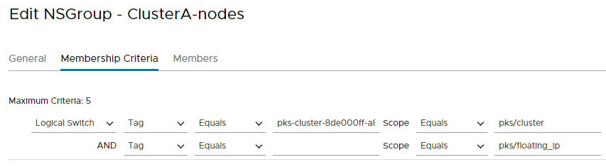
- In the Name field, enter the cluster UUID or cluster name and append
After you configure the NSGroup for cluster nodes, the Membership Criteria tab looks as follows:
Create NSGroup for Cluster Pods
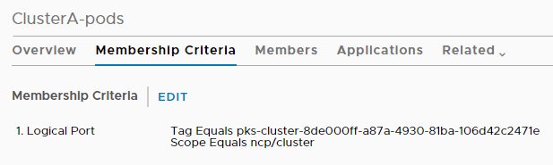
- In NSX Manager, navigate to Inventory > Groups > Groups and click Add new group.
- Configure the new NSGroup as follows:
- In the Name field, enter the cluster UUID or cluster name and append
-podsto the end of the name to distinguish it. The cluster name must be unique. - In the Membership Criteria tab, add the following criterion:
- Select Logical Port.
- For Tag > Equals, enter
tkgi-cluster-YOUR-CLUSTER-UUID. - For Scope > Equals, enter
ncp/cluster.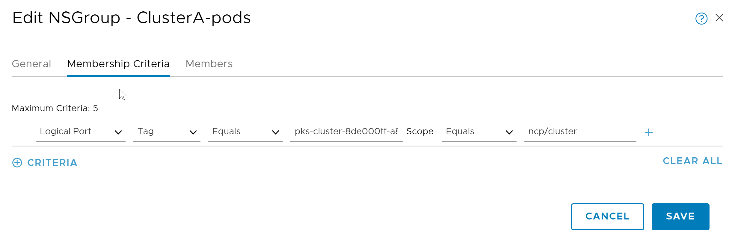
- In the Name field, enter the cluster UUID or cluster name and append
After you configure the NSGroup for cluster pods, the Membership Criteria tab looks as follows:
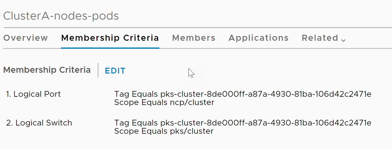
Create NSGroup for Cluster Nodes and Pods
- In NSX Manager, navigate to Inventory > Groups > Groups and click Add new group.
- Configure the new NSGroup as follows:
- In the Name field, enter the cluster UUID or cluster name and append
-nodes-podsto the end of the name to distinguish it. The cluster name must be unique. - In the Membership Criteria tab, add the following two criteria:
- For the first criterion, select Logical Port.
- For Tag > Equals, enter
tkgi-cluster-YOUR-CLUSTER-UUID. - For Scope > Equals, enter
ncp/cluster. - For the second criterion, select Logical Switch.
- For Tag > Equals, enter
tkgi-cluster-YOUR-CLUSTER-UUID. - For Scope > Equals, enter
pks/cluster.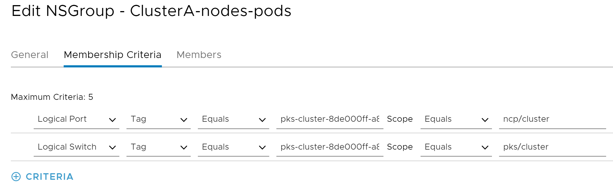
- In the Name field, enter the cluster UUID or cluster name and append
After you configure the NSGroup for cluster nodes and pods, the Membership Criteria tab looks as follows:
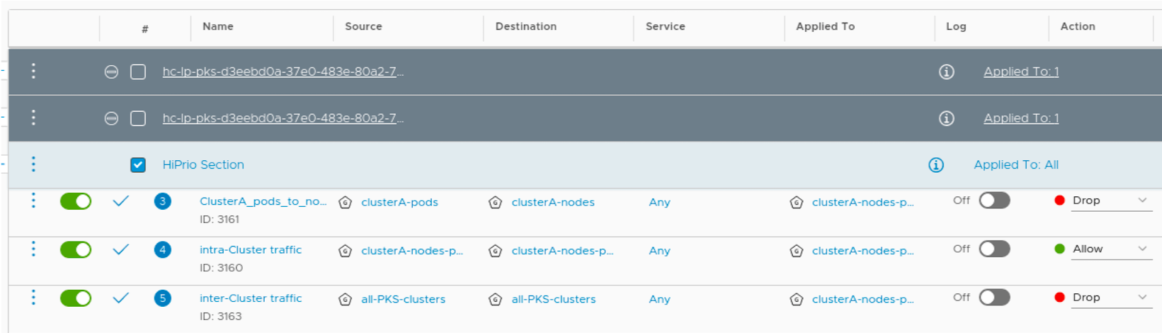
Step 4: Create DFW Rules
Select the DFW section you created above and configure the following three DFW rules:
- Deny Everything Else
- Prevent Pod to Node Communication
- Allow Node to Node and Nodes to Pods Communications
DFW Rule 1: Deny Everything Else
This is a global deny rule. Configure the rule as follows:
- Click Add Rule.
- In the Name field, enter a name for your DFW rule.
- For Source, select the
All-TKGI-ClustersNSGroup. - For Destination, select the
All-TKGI-ClustersNSGroup. - For Service, select Any.
- For Apply To, select the
YOUR-CLUSTER-UUID-nodes-podsNSGroup. - For Action, select Drop.
DFW Rule 2: Prevent Pod to Node Communication
Configure this rule as follows:
- Click Add Rule.
- In the Name field, enter a name for your DFW rule.
- For Source, select the
YOUR-CLUSTER-UUID-podsNSGroup. - For Destination, select
YOUR-CLUSTER-UUID-nodesNSGroup. - For Service, select Any.
- For Apply To, select the
YOUR-CLUSTER-UUID-nodes-podsNSGroup. - For Action, select Drop.
DFW Rule 3: Allow Node to Node and Nodes to Pods Communications
Configure this rule as follows:
- Click Add Rule.
- In the Name field, enter a name for your DFW rule.
- For Source, select the
YOUR-CLUSTER-UUID-nodes-podsNSGroup. - For Destination, select
YOUR-CLUSTER-UUID-nodes-podsNSGroup. - For Service, select Any.
- For Apply To, select
YOUR-CLUSTER-UUID-nodes-podsNSGroup. - For Action, select Allow.
For example, see the three configured DFW rules below:
Configure VRF Tier-0 Gateway-Based Tenant Isolation
To isolate a cluster and its workloads behind a VRF gateway:
- Review Your Network Configuration
- Create VRF Gateway Segments
- Create VRF Gateways
- Create a Network Profile
- Configure a Cluster with a VRF Gateway
Step 1: Review Your Network Configuration
To review the network configuration of your three VLANs:
-
To determine the VLAN IDs of your three VLANs, run either of the following for each VLAN:
-
Method one:
sudo cat /proc/net/vlan/VLAN-NAME |grep VIDWhere VLAN-NAME is the name of a single VLAN.
-
Method two:
ip -d link show dev VLAN-NAME |grep idWhere VLAN-NAME is the name of a single VLAN.
-
-
Confirm that a t0-shared gateway uses the VLAN IDs and that its segment matches the segments returned by the commands above.
Step 2: Create VRF Gateway Segments
You must create two VLAN-backed segments for your VRF gateways. For information on creating a VLAN-backed segment, see Add a Segment in the VMware NSX-T Data Center documentation.
To create two gateway segments:
-
Create a VLAN-backed segment for one of your VRF gateway VLANs with the following configuration:
- Configure Segment Name. For example,
internet-vlan-vrf-0-seg. - Configure Transport Zone. For example,
internet-tz-vlan-0. - Configure VLAN. Specify one of the VLAN IDs determined above.
- Configure Segment Name. For example,
-
Create a VLAN-backed segment for your remaining VRF gateway VLAN with the following configuration:
- Configure Segment Name with a new unique name. For example,
internet-vlan-vrf-1-seg. - Configure Transport Zone with the same zone used by the first segment.
- Configure VLAN with the VLAN ID for the second VLAN.
- Configure Segment Name with a new unique name. For example,
Step 3: Create VRF Gateways
You must create two VRF gateways to isolate your tenants. For information on creating a VRF gateway, see Add a VRF Gateway in the VMware NSX-T Data Center documentation.
-
Create a VRF gateway with the following configuration:
- Provide a Name for the VRF gateway. For example,
t0-vrf-0. - Connect the VRF gateway to your Tier-0 Gateway.
- Save your configuration.
- Set the interface for the gateway. For example,
t0-vrf-0-uplink-0andt0-vrf-0-uplink-1. - Assign a high availability VIP. For example,
192.168.116.2.
- Provide a Name for the VRF gateway. For example,
-
Create a second VRF gateway with the following configuration:
- Configure Name with a unique name. For example,
t0-vrf-1. - Configure Interface with unique settings. For example,
t0-vrf-1-uplink-0andt0-vrf-1-unlink-1. - Configure HA VIP with a unique IP Address. For example,
192.168.117.2.
- Configure Name with a unique name. For example,
-
To test your configuration, Ping each gateway uplink VIP.
For example:
$ ping 192.168.116.2 PING 192.168.116.2 (192.168.116.2) 56(84) bytes of data. 64 bytes from 192.168.116.2: icmp_seq=1 ttl=64 time=0.478 ms 64 bytes from 192.168.116.2: icmp_seq=2 ttl=64 time=0.520 ms ^C --- 192.168.116.2 ping statistics --- 2 packets transmitted, 2 received, 0% packet loss, time 999ms rtt min/avg/max/mdev = 0.478/0.499/0.520/0.021 ms $ ping 192.168.117.2 PING 192.168.117.2 (192.168.117.2) 56(84) bytes of data. 64 bytes from 192.168.117.2: icmp_seq=1 ttl=64 time=0.531 ms 64 bytes from 192.168.117.2: icmp_seq=2 ttl=64 time=0.504 ms ^C --- 192.168.117.2 ping statistics --- 2 packets transmitted, 2 received, 0% packet loss, time 999ms rtt min/avg/max/mdev = 0.504/0.517/0.531/0.026 ms -
(Optional) To allow communication to an external data path, add a default router for each VRF gateway. For each router, add a default route and configure Network and Next Hop.
Step 4: Create a Network Profile
You must use a Network Profile to isolate a cluster behind a VRF gateway.
To configure a Network Profile for connecting to a VRF gateway:
-
Create a network profile configuration JSON file that defines the gateway as the
"t0_router_id"value:{ "name": "PROFILE-NAME", "description": "PROFILE-DESCRIP", "parameters": { "t0_router_id":"VRF-GATEWAY-NAME", "infrastructure_networks":[NETWORK-RANGES], "cni_configurations": { "type": "nsxt", "parameters": { "extensions":{ "ncp":{ "nsx_v3":{ }, "coe":{ }, "ha":{ }, "k8s":{ } }, "nsx-node-agent":{ } } } } } }Where:
VRF-GATEWAY-NAMEis the name of the VRF gateway for the cluster to use.NETWORK-RANGESis an array of IP ranges the cluster can access.PROFILE-NAMEis the internal name for your network profile.PROFILE-DESCRIPis an internal description for your network profile.
For example:
{
    "name": "np-1",
    "description": "",
    "parameters": {

        "t0_router_id":"vrf-103",
        "infrastructure_networks":["88.0.0.0/24","192.168.111.98","192.168.111.46"],
        "cni_configurations": {
            "type": "nsxt",
            "parameters": {

                "extensions":{
                    "ncp":{
                        "nsx_v3":{
                        },
                        "coe":{
                        },
                        "ha":{
                        },
                        "k8s":{
                        }
                    },
                    "nsx-node-agent":{
                    }
                }
            }
        }
    }
}
For more information on creating a Network Profile, see Creating and Managing Network Profiles.
Step 5: Configure a Cluster with a VRF Gateway
To configure a cluster to use a VRF gateway, assign the Network Profile to the cluster:
-
Create a new cluster using the VRF gateway Network Profile.
For more information on creating clusters using a Network Profile, see Create a Cluster with a Network Profile in Using Network Profiles.
-
Update an existing cluster using the VRF gateway Network Profile.
For more information on updating existing clusters with a Network Profile, see Assign a Network Profile to an Existing Cluster in Using Network Profiles.
