This topic describes options for configuring VMware Tanzu Kubernetes Grid Integrated Edition (TKGI) on vSphere to support stateful apps using PersistentVolumes (PVs).
Note: This topic assumes that you have strong familiarity with PVs and workloads in Kubernetes.
For procedural information about configuring PVs, see Configuring and Using PersistentVolumes.
For information about which vSphere CSI Driver features are supported by TKGI, see vSphere CSI Driver Supported Features and Requirements in Deploying and Managing Cloud Native Storage (CNS) on vSphere.
Considerations for Running Stateful Apps in Kubernetes
There are several factors to consider when running stateful apps in Kubernetes:
- Pods are ephemeral by nature. Data that needs to be persisted must be accessible on restart and rescheduling of a pod.
- When a pod is rescheduled, it might be on a different host. Storage must be available on the new host for the pod to start gracefully.
- The app should not manage the volume and data. The underlying infrastructure will handle the complexity of unmounting and mounting.
- Certain apps have a strong sense of identity. When a container with a certain ID uses a disk, the disk becomes tied to that container. If a pod with a certain ID gets rescheduled, the disk associated with that ID must be reattached to the new pod instance.
Persistent Volume Provisioning, Static and Dynamic
Kubernetes provides two ways to provision persistent storage for stateful applications:
- Static provisioning: A Kubernetes administrator creates the Virtual Machine Disk (VMDK) and PVs. Developers issue PersistentVolumeClaims (PVCs) on the pre-defined PVs.
- Dynamic provisioning: Developers issue PVCs against a StorageClass object. The provisioning of the persistent storage depends on the infrastructure. With Tanzu Kubernetes Grid Integrated Edition on vSphere, the vSphere Cloud Provider (VCP) automatically provisions the VMDK and PVs.
For more information about PVs in Kubernetes, refer to the Kubernetes documentation.
PVs can be used with two types of Kubernetes workloads:
Migrating Persistent Volumes Between Datastores Provisioning Support in Kubernetes
On vSphere 8U2+ and 73o+, Kubernetes CSI PersistentVolumes (PVs) used by TKGI clusters can be migrated between datastores.
Migration is supported for all vSphere CSI-managed block PVs, including PVs created by CSI and migrated from in-tree storage to CSI.
Requirements:
- TKGI 1.16 and later
- vSphere 8.0 Update 2 and later or 7.0 Update 3o and later
- Source and target datastores must have the same host accessibility, especially if you have the CSI zoning feature enabled as described in Deploying vSphere Container Storage Plug-in with Topology
Limitations: See Guidelines/Limitations for Cloud Native Storage (CNS) Relocate on vSphere and known issues in the Broadcom Support Knowledge Base.
Migration procedures:
- vSphere 8.0 U2 and later: Migrating Container Volumes in vSphere.
- vSphere 7.0 U3o and later: Migrating Container Volumes in vSphere
Storage Scenarios for Compute Clusters and File Systems
With Tanzu Kubernetes Grid Integrated Edition on vSphere, you can choose one of two storage options to support stateful apps:
- vSAN datastores
- Network File Share (NFS) or VMFS over Internet Small Computer Systems Interface (iSCSI), or fiber channel (FC) datastores
Refer to the vSAN documentation and the VMFS documentation for more information about these storage options.
Note: This topic assumes that you have strong familiarity vSAN and VMFS storage technologies on the vSphere platform.
In Tanzu Kubernetes Grid Integrated Edition, an availability zone (AZ) corresponds to a vSphere cluster and a resource pool within that cluster. A resource pool is a vSphere construct that is not linked to a particular ESXi host. Resource pools can be used in testing environments to enable a single vSphere cluster to support multiple AZs. As a recommended practice, deploy multiple AZs across different vSphere clusters to afford best availability in production.
The vSAN datastore boundary is delimited by the vSphere cluster. All ESXi hosts in the same vSphere cluster belong to the same vSAN datastore. ESXi hosts in a different vSphere cluster belong to a different vSAN datastore. Each vSphere cluster has its own vSAN datastore.
The table below summarizes Tanzu Kubernetes Grid Integrated Edition support for PVs in Kubernetes when deployed on vSphere:
| Storage Mechanism | vSAN datastore | File system datastore (VMFS/NFS over iSCSI/FC) |
|---|---|---|
|
Both static and dynamic PV provisioning are supported. | Both static and dynamic PV provisioning are supported. |
|
Neither static nor dynamic PV provisioning are supported. | Neither static nor dynamic PV provisioning are supported. |
|
vSAN does not support sharing datastores across vSphere clusters. Can be accomplished by providing vSphere clusters with access to additional shared storage such as VMFS/NFS over iSCSI/FC. | Both static and dynamic PV provisioning are supported. |
Note: This information assumes that the underlying vSphere infrastructure is a single locality environment where all vSphere compute clusters are closed in terms of distance from one to the others. It does not apply to multi-site or vSAN Stretched Cluster configurations.
Single vSphere Compute Cluster with vSAN Datastore
The following diagram illustrates a vSphere environment with a single compute cluster and a local vSAN datastore. This topology is also supported for environments with a single AZ or multiple AZs using multiple resource pools under the same vSphere cluster. For this topology, Tanzu Kubernetes Grid Integrated Edition supports both static and dynamic PV provisioning. Dynamic PV provisioning is recommended.
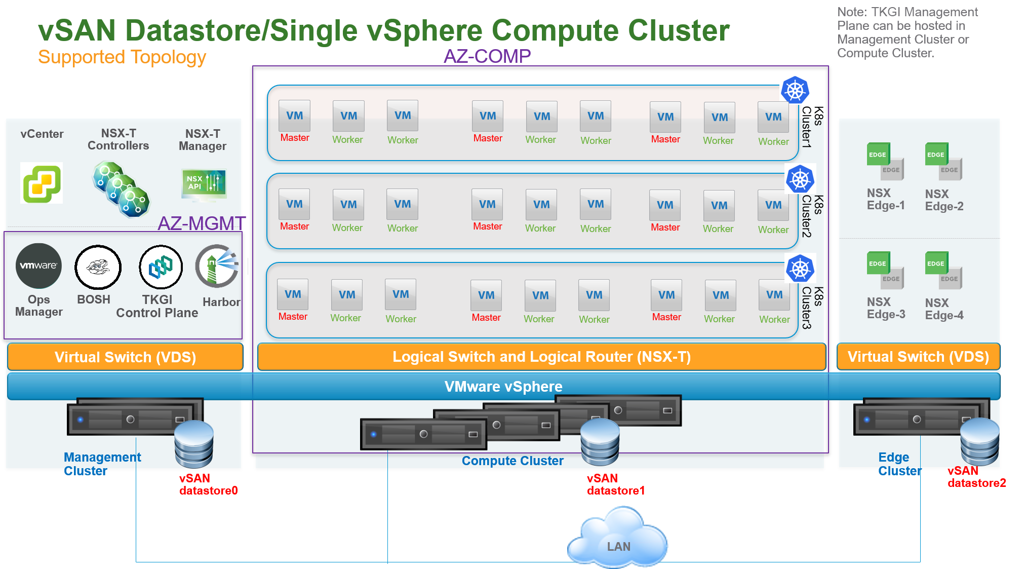
In this topology, a single vSphere compute cluster hosts all Kubernetes clusters. vSAN is enabled on the compute cluster which exposes a single unique vSAN datastore. In the above diagram, this datastore is labeled vSAN datastore1.
You can configure a single computer cluster in the following ways:
- If you use a single Tanzu Kubernetes Grid Integrated Edition foundation, create an AZ that is mapped directly to the single cluster.
- If you use multiple Tanzu Kubernetes Grid Integrated Edition foundations, create an AZ that is mapped to this single cluster and a Resource Pool.
With this topology, you can create multiple vSAN datastores on the same compute cluster using different disk groups on each ESXi host. PVs, backed by respective VMDK files, can be dispatched across the datastores to mitigate the impact of datastore failure. For StatefulSets, all PVs used by different instances of the replica land in the same datastore.
This topology has the following failover scenarios:
- Disks on ESXi hosts are down: If the failure is within the limit of the vSAN
failure to toleratevalue, there is no impact on PVs. - ESXi hosts are down: If the failure is within the limit of the vSAN
failure to toleratevalue, there is no impact on PVs. - Datastore is down: PVs on the down datastore are unreachable.
Single vSphere Compute Cluster with File System Datastore
The following diagram illustrates a vSphere environment with a single vSphere compute cluster and a shared datastore using NFS or VMFS over iSCSI, or FC. For this topology, Tanzu Kubernetes Grid Integrated Edition supports both static and dynamic PV provisioning. Dynamic PV provisioning is recommended.
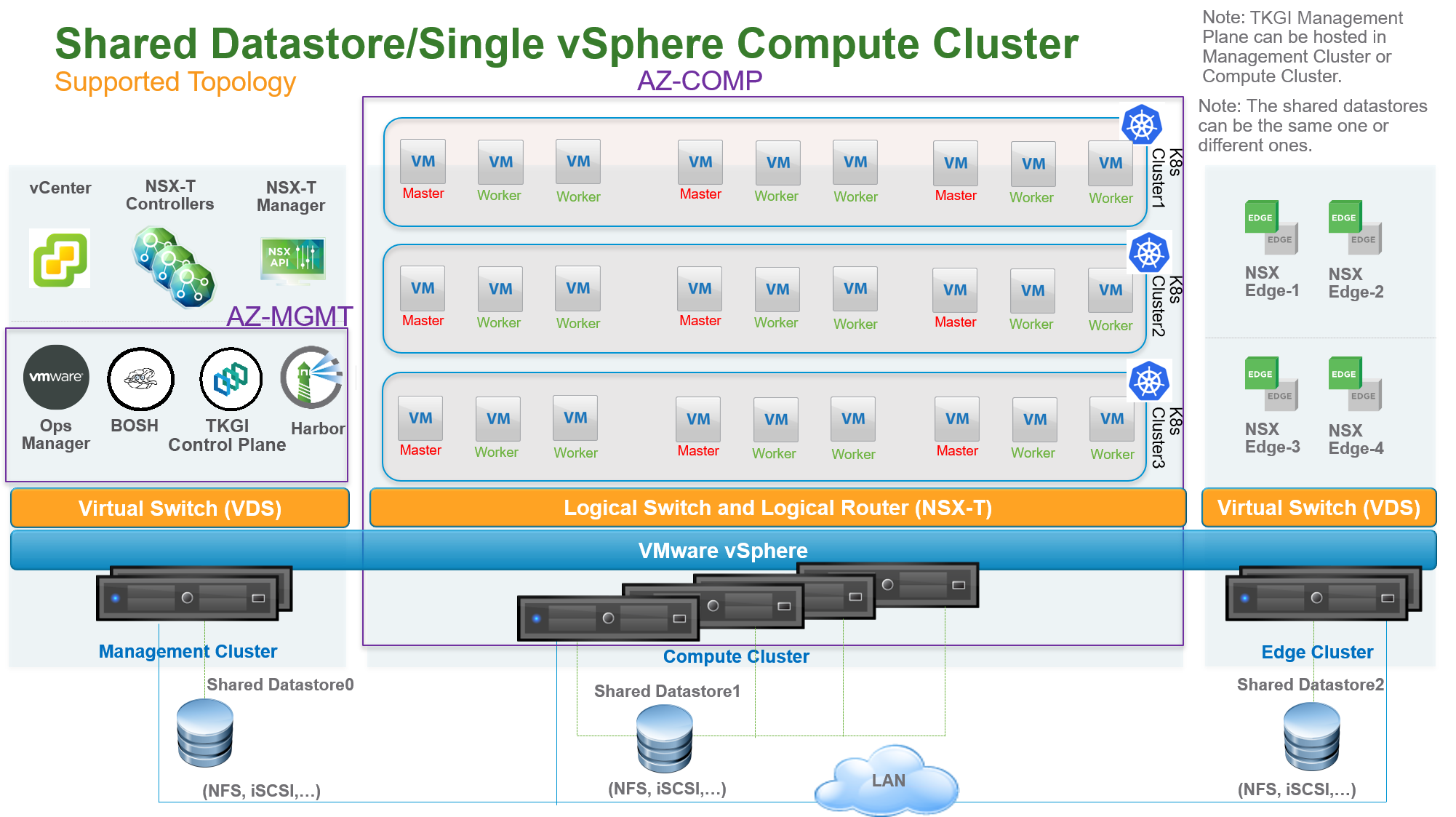
In this topology, a single vSphere compute cluster hosts all Kubernetes clusters. The shared datastore is used with the compute cluster. In the above diagram, this datastore is labeled Shared Datastore1.
One or more AZs can be instantiated on top of the compute cluster. With this configuration, one or more AZs are mapped to vSphere resource pools. The AZ is not bound to a failure domain because its resource pool is not linked to a particular ESXi host.
With this topology, you can create multiple shared datastores connected to the same compute cluster. PVs, backed by respective VMDK files, can be dispatched across the datastores to mitigate the impact of datastore failure. For StatefulSets, all PVs used by different instances of the replica land in the same datastore.
This topology has the following failover scenarios:
- ESXi hosts are down: No impact on PVs.
- Datastore is down: PVs on the down datastore are unreachable.
Multiple vSphere Compute Clusters Each with vSAN Datastore
The following diagram illustrates a vSphere environment with multiple vSphere compute clusters with vSAN datastores that are local to each compute cluster.
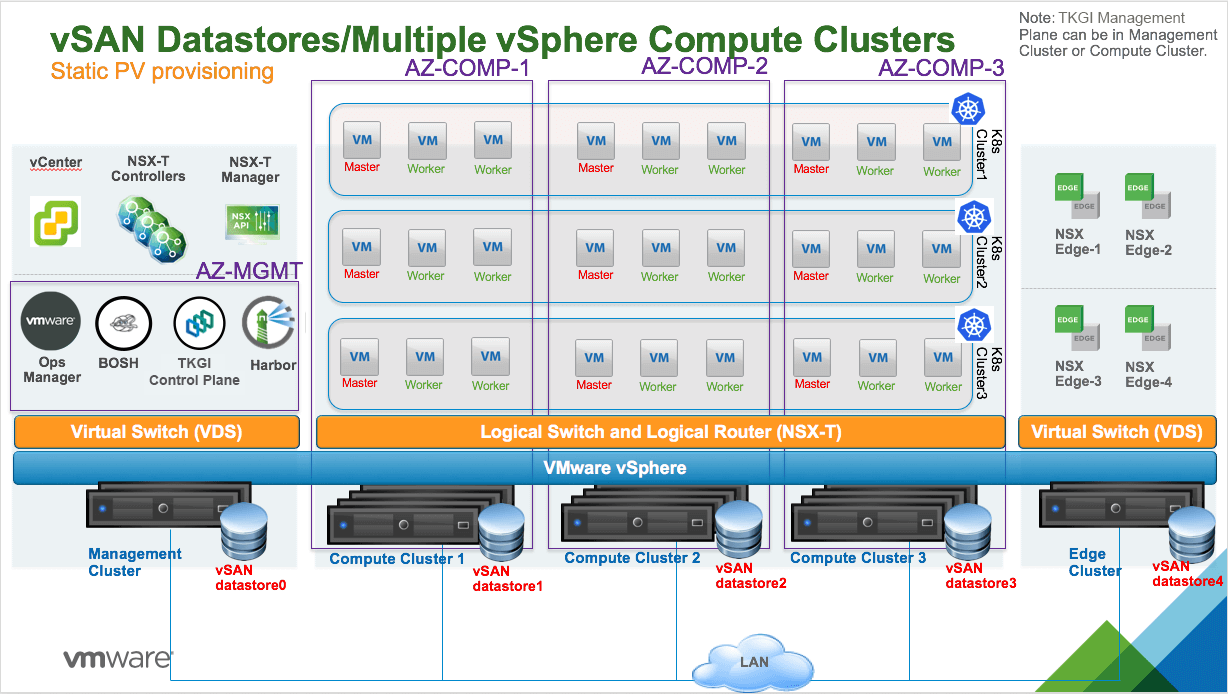
In this topology, vSAN is enabled on each compute cluster. There is one local vSAN datastore per compute cluster. For example, in the above diagram, vSAN datastore1 is provisioned for Compute Cluster 1 and vSAN datastore2 is provisioned for Compute Cluster 2.
One or more AZs can be instantiated. Each AZ is mapped to a vSphere compute cluster. The AZ is bound to a failure domain which is typically the physical rack where the compute cluster is hosted.
Multiple vSphere Compute Clusters Each with File System Datastore
The following diagram illustrates a vSphere environment with multiple vSphere compute clusters with NFS or VMFS over iSCSI, or FC shared datastores.
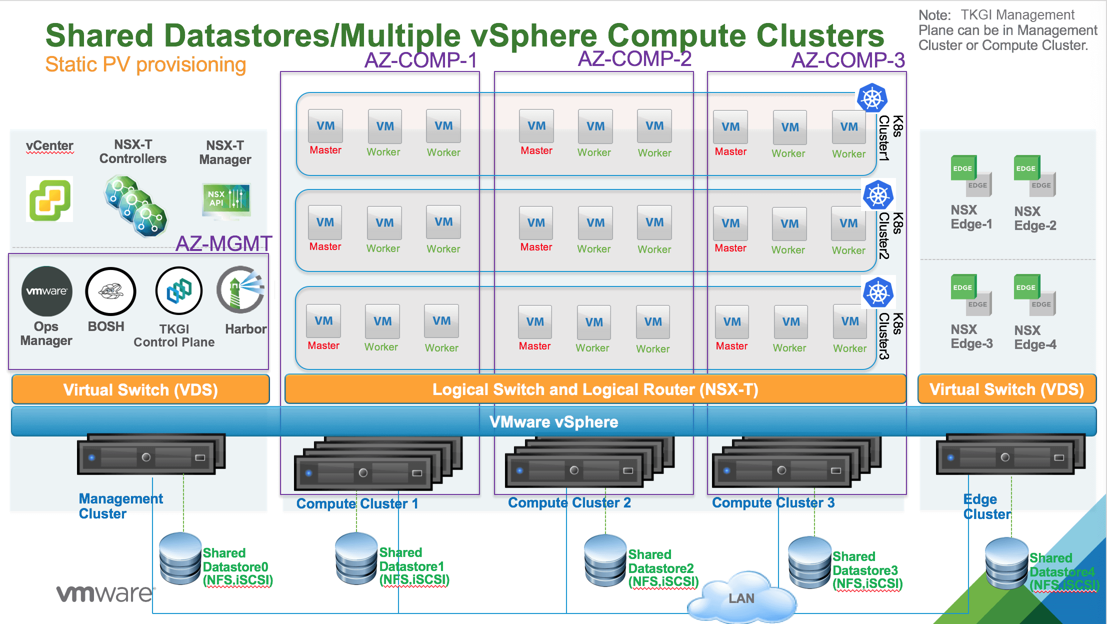
In this topology, multiple vSphere compute clusters are used to host all Kubernetes clusters. A unique shared datastore is used per vSphere compute cluster. For example, in the above diagram, Shared Datastore1 is connected to Compute Cluster 1 and Shared Datastore2 is connected to Compute Cluster 2.
One or more AZs can be instantiated. Each AZ is mapped to a vSphere compute cluster. The AZ is bound to a failure domain which is typically the physical rack where the compute cluster is hosted.
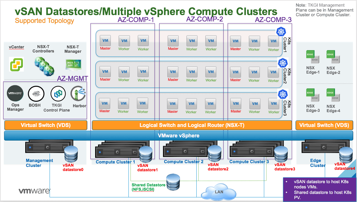
Multiple vSphere Compute Clusters with Local vSAN and Shared File System Datastore
With this topology, each vSAN datastore is only visible from each vSphere compute cluster. It is not possible to have a vSAN datastore shared across all vSphere compute clusters.
You can insert a shared NFS, iSCSI (VMFS), or FC (VMFS) datastore across all vSAN-based vSphere compute clusters to support both static and dynamic PV provisioning.
Refer to the following diagram:
Multiple vSphere Compute Clusters with Shared File System Datastore
The following diagram illustrates a vSphere environment with multiple compute clusters with VMFS over NFS, iSCSI, or FC datastores shared across all vSphere compute clusters. For this topology, Tanzu Kubernetes Grid Integrated Edition supports both static and dynamic PV provisioning. Dynamic PV provisioning is recommended.
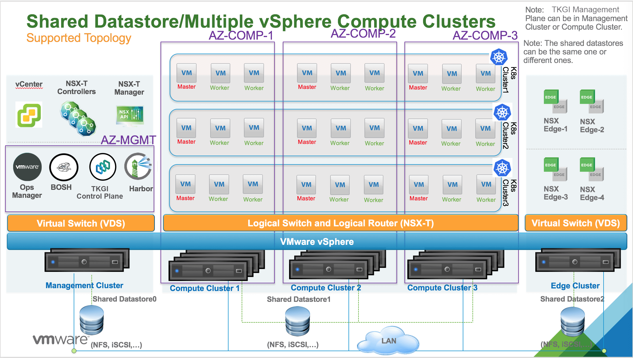
In this topology, multiple vSphere compute clusters are used to host all Kubernetes clusters. A unique shared datastore that uses NFS, or VMFS over iSCSI/FC is used across all compute clusters. In the above diagram, this datastore is labeled Shared Datastore1.
One or more AZs can be instantiated. Each AZ is mapped to a compute cluster. The AZ is bound to a failure domain which is typically the physical rack where the compute cluster is hosted.
You can have multiple shared datastores connected across all the vSphere compute clusters. PVs, backed by respective VMDK files, can then be dispatched across those datastores to mitigate the impact of datastore failure. For StatefulSets, all PVs used by different instances of the replica land in the same datastore.
This topology has the following failover scenarios:
- ESXi hosts are down: No impact on PVs.
- One shared datastore is down: PVs on the down datastore are unreachable.