


You must follow these steps before you install VMware Tanzu Operations Manager on Google Cloud Platform (GCP).
Prerequisites
Before you prepare your Tanzu Operations Manager installation, do the following tasks depending on the runtime you intend to deploy:
-
If you are deploying VMware Tanzu Application Service for VMs (TAS for VMs), see Tanzu Operations Manager on GCP Requirements.
-
If you are deploying Enterprise VMware Tanzu Kubernetes Grid Integrated Edition (TKGI), see GCP Prerequisites and Resource Requirements.
Configuration and components
This section outlines high-level infrastructure options for Tanzu Operations Manager on GCP. A Tanzu Operations Manager deployment includes Tanzu Operations Manager and your chosen runtime. For example, both Tanzu Operations Manager with TAS for VMs and Tanzu Operations Manager with TKGI are Tanzu Operations Manager deployments. For more information, review the deployment options and recommendations in Reference architecture for Tanzu Operations Manager on GCP.
You can deploy Tanzu Operations Manager using one of two main configurations on a GCP virtual private cloud (VPC):
- A single-project configuration that gives Tanzu Operations Manager full access to VPC resources
- A shared VPC configuration in which Tanzu Operations Manager shares VPC resources
See Shared vs Single-Project VPCs in Reference Architecture for Tanzu Operations Manager on GCP for a full discussion and recommendations.
When deploying Tanzu Operations Manager on GCP, VMware recommends using the following GCP components:
- Google Cloud SQL for external database services
- NAT Gateway Instances to limit the number of VMs with public IP addresses
- Google Cloud Storage for external file storage
Step 1: Set up IAM service accounts
Tanzu Operations Manager uses IAM service accounts to access GCP resources.
For a single-project installation: Complete the following steps to create a service account for Tanzu Operations Manager.
For a shared-VPC installation: Complete the following steps twice, to create a host account and service account for Tanzu Operations Manager.
-
From the GCP console, click IAM & Admin, then Service accounts.
-
Click Create Service Account:
-
Service account name: Enter a name. For example,
bosh. -
Role: Use the drop-down menu, select the following roles: *Service Accounts, then Service Account User * Service Accounts, then Service Account Token Creator *Compute Engine, then Compute Instance Admin (v1) * Compute Engine, then Compute Network Admin *Compute Engine, then Compute Storage Admin * Storage, then Storage Admin
You must scroll down in the pop-up windows to select all required roles.
The Service Account User role is required only if you plan to use The Tanzu Operations Manager VM Service Account to deploy Tanzu Operations Manager. For more information about The Tanzu Operations Manager VM Service Account, see Step 2: Google Cloud Platform Config in Configuring BOSH Director on GCP.- Service account ID: The text box automatically generates a unique ID based on the username.
-
Furnish a new private key: Select this check box and JSON as the Key type.

-
Click Create. Your browser automatically downloads a JSON file with a private key for this account. Save this file in a secure location. You can use this service account to configure file storage for TAS for VMs. For more information, see GCP in Configuring File Storage for TAS for VMs.
Step 2: Enable Google Cloud APIs
Tanzu Operations Manager manages GCP resources using the Google Compute Engine and Cloud Resource Manager APIs. To enable these APIs:
-
Log in to the Google Developers Console at https://console.developers.google.com.
-
In the console, go to the GCP projects where you want to install Tanzu Operations Manager.
-
For a single-project installation, complete the following steps for the Tanzu Operations Manager project.
-
For a shared-VPC installation, complete the following steps for both host and service projects, to enable them to access the Google Cloud API.
-
Click API Manager, then Library.
-
Under Google Cloud APIs, click Compute Engine API.
-
On the Google Compute Engine API pane, click Enable.
-
In the search text box, enter
Google Cloud Resource Manager API. -
On the Google Cloud Resource Manager API pane, click Enable.
-
To verify that the APIs have been enabled, complete the following steps:
-
Log in to GCP using the IAM service account you created in Set up IAM Service Accounts:
$ gcloud auth activate-service-account --key-file JSON_KEY_FILENAME
-
List your projects:
$ gcloud projects list
PROJECT_ID              NAME                      PROJECT_NUMBER
my-host-project-id      my-host-project-name      ##############
my-service-project-id   my-service-project-name   ##############
This command lists the projects where you enabled Google Cloud APIs.
-
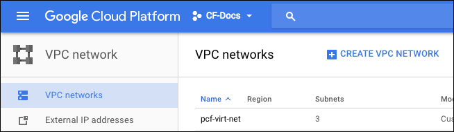
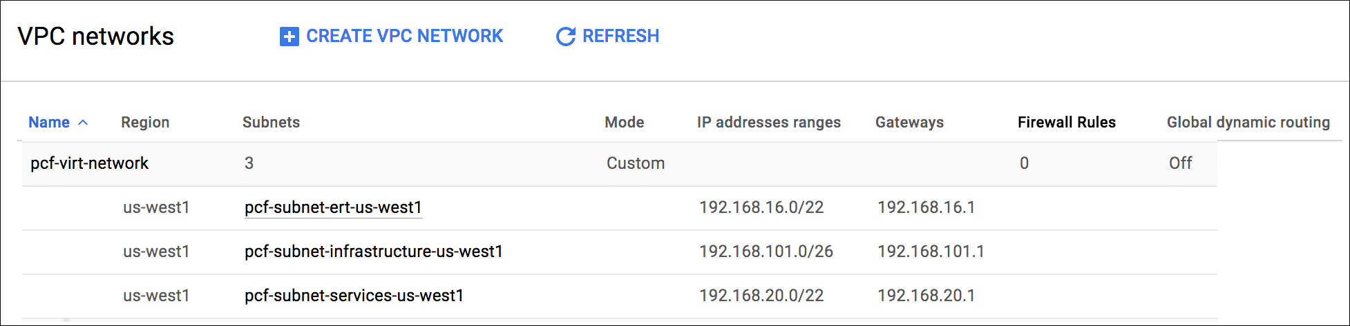
Step 3: Create a GCP network with subnets
-
Log in to the GCP console.
-
Go to the GCP project where you want to install Tanzu Operations Manager. For a shared VPC installation, go to the host project.
-
Click VPC network, then CREATE VPC NETWORK.
-
In the Name text box, enter a name of your choice for the VPC network. This name helps you identify resources for this deployment in the GCP console. Network names must be lowercase. For example,
pcf-virt-net.-
Under Subnets, complete the form as follows to create an infrastructure subnet for Tanzu Operations Manager and NAT instances:
Name pcf-infrastructure-subnet-GCP-REGION
Example:pcf-infrastructure-subnet-us-west1Region A region that supports three availability zones. For help selecting the correct region for your deployment, see the Google documentation about regions and zones. IP address range A CIDR ending in /26
Example:192.168.101.0/26See the following image for an example:
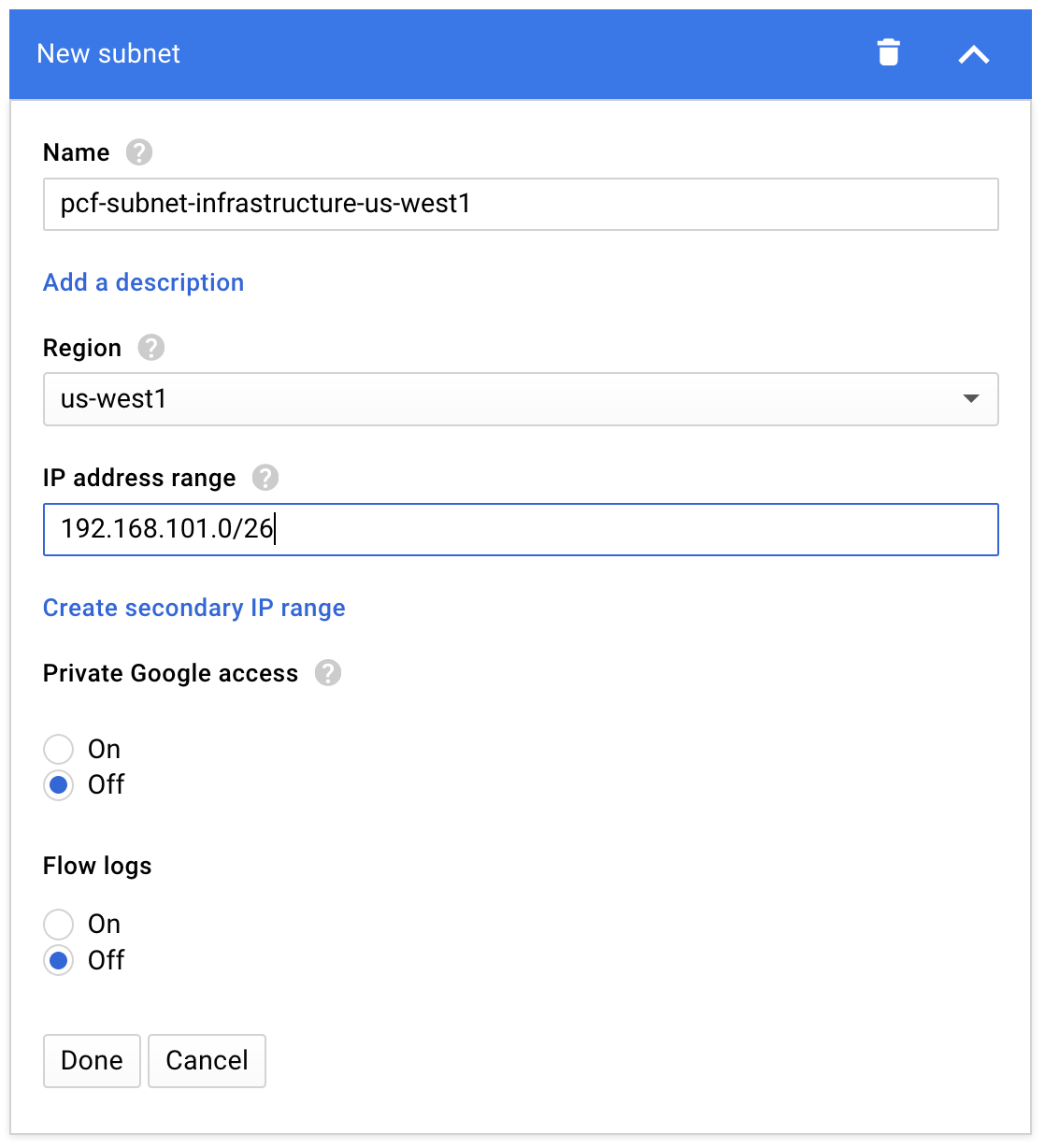
For deployments that do not use external IP addresses, enable Private Google access to allow your runtime to make API calls to Google services.
-
Click Add subnet to add a second subnet for the BOSH Director and components specific to your runtime. Complete the form as follows:
Name pcf-RUNTIME-subnet-GCP-REGION
Example:pcf-pas-subnet-us-west1Region The same region you selected for the infrastructure subnet IP address range A CIDR ending in /22
Example:192.168.16.0/22 -
Click Add subnet to add a third Subnet with the following details:
Name pcf-services-subnet-GCP-REGION
Example:pcf-services-subnet-us-west1Region The same region you selected for the previous subnets IP address range A CIDR in /22
Example:192.168.20.0/22See the following image for an example:
-
-
Under Dynamic routing mode, leave Regional selected.
-
Click Create.
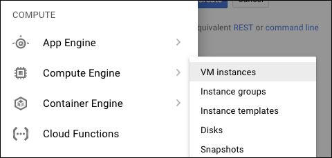
Step 4: Create NAT instances
Use NAT instances when you want to expose only a minimal number of public IP addresses.
Creating NAT instances permits internet access from cluster VMs. You might, for example, need this internet access for pulling Docker images or enabling internet access for your workloads.
For more information, see Reference Architecture for Tanzu Operations Manager on GCP and the GCP documentation.
-
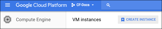
In the GCP console, with your single project or shared-VPC host project selected, navigate to Compute Engine, then VM instances.
-
Click CREATE INSTANCE.
-
Complete the following text boxes:
- Name: Enter
pcf-nat-gateway-pri.
This is the first, or primary, of three NAT instances you need. If you use a single AZ, you need only one NAT instance. - Zone: Click the first zone from your region.
Example: For regionus-west1, clickus-west1-azone. - Machine type: Click
n1-standard-4. - Boot disk: Click Change and click
Ubuntu 14.04 LTS.

- Name: Enter
-
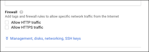
Expand the additional configuration text boxes by clicking Management, disks, networking, SSH keys.
-
In the Startup script text box under Automation, enter the following text:
#! /bin/bash
sudo sysctl -w net.ipv4.ip_forward=1
sudo sh -c 'echo net.ipv4.ip_forward=1 >> /etc/sysctl.conf'
sudo iptables -t nat -A POSTROUTING -o eth0 -j MASQUERADE
-
-
Click Networking to open additional network configuration text boxes:
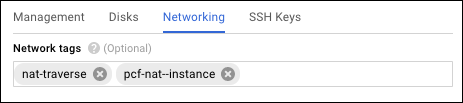
- In the Network tags text box, add the following:
nat-traverseandpcf-nat-instance. - Click the Networking tab and the pencil icon to edit the Network interface.
- For Network, click
pcf-virt-net. You created this network in Step 1: Create a GCP Network with Subnets. - For Subnetwork, click
pcf-infrastructure-subnet-GCP-REGION. -
For Primary internal IP, click
Ephemeral (Custom). Enter an IP address, for example,192.168.101.2, in the Custom ephemeral IP address text box. The IP address must meet the following requirements:- The IP address must exist in the CIDR range you set for the
pcf-infrastructure-subnet-GCP-REGIONsubnet. - The IP address must exist in a reserved IP range set later in BOSH Director. The reserved range is typically the first
.1through.9addresses in the CIDR range you set for thepcf-infrastructure-subnet-GCP-REGIONsubnet. - The IP address cannot be the same as the Gateway IP address set later in Tanzu Operations Manager. The Gateway IP address is typically the first
.1address in the CIDR range you set for thepcf-infrastructure-subnet-GCP-REGIONsubnet.
- The IP address must exist in the CIDR range you set for the
-
For External IP, click
Ephemeral.If you select a static external IP address for the NAT instance, then you can use the static IP to further secure access to your CloudSQL instances.
-
Set IP forwarding to
On. - Click Done.
- In the Network tags text box, add the following:
-
Click Create to finish creating the NAT instance.
-
Repeat steps 2 through 6 to create two additional NAT instances with the names and zones specified in the following table. The rest of the configuration remains the same.
Instance 2 Name pcf-nat-gateway-secZone Select the second zone from your region.
Example: For regionus-west1, select zoneus-west1-b.
Internal IP Select Customand enter an IP address in the Internal IP address text box. Example:192.168.101.3.
As described previously, this address must in the CIDR range you set for thepcf-infrastructure-subnet-GCP-REGIONsubnet, must exist in a reserved IP range set later in BOSH Director, and cannot be the same as the Gateway IP address set later in Tanzu Operations Manager.Instance 3 Name pcf-nat-gateway-terZone Select the third zone from your region.
Example: For regionus-west1, select zoneus-west1-c.Internal IP Select Customand enter an IP address in the Internal IP address text box. Example:192.168.101.4.
As previously described, this address must in the CIDR range you set for thepcf-infrastructure-subnet-GCP-REGIONsubnet, must exist in a reserved IP range set later in BOSH Director, and cannot be the same as the Gateway IP address set later in Tanzu Operations Manager.
Create routes for NAT instances
-
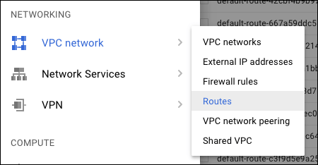
Navigate to VPC Networks, then Routes.
-
Click CREATE ROUTE.
-
Complete the form as follows:
- Name:
pcf-nat-pri - Network:
pcf-virt-net - Destination IP range:
0.0.0.0/0 - Priority:
800 - Instance tags:
pcf - Next hop:
Specify an instance - Next hop instance:
pcf-nat-gateway-pri
- Name:
-
Click Create to finish creating the route.
-
Repeat steps 2 through 4 to create two additional routes with the names and next hop instances specified in the following table. The rest of the configuration remains the same.
Route 2 Name: pcf-nat-sec
Next hop instance:pcf-nat-gateway-secRoute 3 Name: pcf-nat-ter
Next hop instance:pcf-nat-gateway-ter
Step 5: Create firewall rules for the network
GCP lets you assign tags to VM instances and create firewall rules that apply to VMs based on their tags. For more information about tags, see Labeling Resources in the GCP documentation. This step assigns tags and firewall rules to Tanzu Operations Manager components and VMs that handle incoming traffic.
-
With your single project or shared-VPC host project selected, go to the Networking, then VPC network pane and select Firewall rules.
-
Apply the firewall rules in the following table:
Firewall Rules Rule 1 This rule allows SSH from public networks.
Name:pcf-allow-ssh
Network:pcf-virt-net
Allowed protocols and ports:tcp:22
Source filter: IP ranges
Source IP ranges:0.0.0.0/0
Target tags:allow-sshRule 2 This rule allows HTTP from public networks.
Name:pcf-allow-http
Network:pcf-virt-net
Allowed protocols and ports:tcp:80
Source filter: IP ranges
Source IP ranges:0.0.0.0/0
Target tags:allow-http,routerRule 3 This rule allows HTTPS from public networks.
Name:pcf-allow-https
Network:pcf-virt-net
Allowed protocols and ports:tcp:443
Source filter: IP ranges
Source IP ranges:0.0.0.0/0
Target tags:allow-https,routerRule 4 This rule allows Gorouter health checks.
Name:pcf-allow-http-8080
Network:pcf-virt-net
Allowed protocols and ports:tcp:8080
Source filter: IP ranges
Source IP Ranges:0.0.0.0/0
Target tags:routerRule 5 This rule allows communication between BOSH-deployed jobs.
Name:pcf-allow-pas-all
Network:pcf-virt-net
Allowed protocols and ports:tcp;udp;icmp
Source filter: Source tags
Target tags:pcf,pcf-opsman,nat-traverse
Source tags:pcf,pcf-opsman,nat-traverseRule 6 (Optional) This rule allows access to the TCP router.
Name:pcf-allow-cf-tcp
Network:pcf-virt-net
Source filter: IP ranges
Source IP ranges:0.0.0.0/0
Allowed protocols and ports:tcp:1024-65535
Target tags:pcf-cf-tcpRule 7 (Optional) This rule allows access to the SSH proxy.
Name:pcf-allow-ssh-proxy
Network:pcf-virt-net
Source filter: IP ranges
Source IP ranges:0.0.0.0/0
Allowed protocols and ports:tcp:2222
Target tags:pcf-ssh-proxy,diego-brain
If you want your firewall rules to only permit traffic within your private network, modify the Source IP Ranges from the table accordingly.
-
If you are only using your GCP project to deploy Tanzu Operations Manager, then you can delete the following default firewall rules:
default-allow-httpdefault-allow-httpsdefault-allow-icmpdefault-allow-internaldefault-allow-rdpdefault-allow-ssh
If you are deploying TKGI only, continue to Next steps.
If you are deploying TAS for VMs or other runtimes, proceed to the following step.
Step 6: Create database instance and databases
Create database instance
-
For a shared-VPC installation, click the service project in the GCP console. This step and the following steps allocate resources to the service project, not the host project.
-
From the GCP console, click SQL and click CREATE INSTANCE.
-
Ensure MySQL is selected and click Next.
-
Under MySQL, click Second Generation instance type.
-
Click Configure MySQL under your choice for instance type: Development, Staging, or Production.
-
Configure the instance as follows:
- Instance ID:
pcf-pas-sql - Root password: Set a password for the root user.
- Region: Select the region you specified when creating networks.
- Zone: Any.
- Configure machine type and storage:
- Click Change and then select db-n1-standard-2.
- Ensure that Enable automatic storage increases is selected. This allows DB storage to grow automatically when space is required.
- Enable auto backups and high availability: Make the following selections:
- Leave Automate backups and Enable binary logging selected.
- Under High availability, select the Create failover replica check box.
-
Authorize Networks: Click Add network and create a network named
allthat allows traffic from0.0.0.0/0.If you assigned static IP addresses to your NAT instances, you can instead limit access to the database instances by specifying the NAT IP addresses.
- Instance ID:
-
Click Create.
Create databases
-
Go to the Instances page and select the database instance you just created.
-
Select the Databases tab.
-
Click Create database to create the following databases:
accountapp_usage_serviceautoscaleccdbconsolediegolocketnetworkpolicyservernfsvolumenotificationsroutingsilkuaacredhub
-
Select the USERS tab.
-
Click Create user account to create a unique username and password for each database you created above. For Host name, select Allow any host. You must create a total of fourteen user accounts.
Ensure that the networkpolicyserver database user has the ALL PRIVILEGES permission.
Step 7: Create storage buckets
-
With your single project or shared-VPC service project selected in the GCP console, click Storage, then Browser.
-
Using CREATE BUCKET, create buckets with the following names. For Default storage class, click Multi-Regional:
PREFIX-pcf-buildpacksPREFIX-pcf-dropletsPREFIX-pcf-packagesPREFIX-pcf-resourcesPREFIX-pcf-backup
Where
PREFIXis a prefix of your choice, required to make the bucket name unique.
Step 8: Create HTTP load balancer
For load balancing, you can use a global HTTP load balancer or an internal, regional load balancer with a private IP address.
Single project, standalone installations typically use a global HTTP load balancer. For more information, see Create HTTP Load Balancer on how to set this up.
Shared-VPC installation typically use an internal TCP/UDP load balancer to minimize public IP addresses. For more information, see Create Internal Load Balancer below for how to set this up.
Create internal load balancer
To create an internal load balancer for Tanzu Operations Manager on GCP, do the following.
-
Create an internal-facing TCP/UDP load balancer for each region of your Tanzu Operations Manager deployment.
GCP Internal Load Balancer (iLB) is a regional product. Within the same VPC/network, client VMs in a different region from the iLB cannot access the iLB. For more information, see the GCP documentation.
-
Assign private IP addresses to the load balancers.
-
After you have deployed Tanzu Operations Manager, follow instructions in Create or Update a VM Extension to add a custom VM extension that applies internal load balancing to all VMs deployed by BOSH.
-
For example, the following manifest code adds a VM extension
backend-poolto Tanzu Operations Manager VMs:vm_extensions: - name: backend-pool cloud_properties: ephemeral_external_ip: true backend_service: name: name-of-backend-service scheme: INTERNAL
-
Create HTTP load balancer
To create a global HTTP load balancer for Tanzu Operations Manager on GCP:
Create instance group
-
Go to Compute Engine, then Instance groups.
-
Click CREATE INSTANCE GROUP.
-
Complete the form as follows:
-
For Name, enter
pcf-http-lb - For Location, click Single-zone.
- For Zone, click the first zone from your region.
Example: For regionus-west1, click zoneus-west1-a. - Under Group type, click Unmanaged instance group.
- For Network, click
pcf-virt-net. - For Subnetwork, click the
pcf-pas-subnet-my-gcp-regionsubnet that you created previously. -
Click Create.
-
Create a second instance group with the following details:
-
Name:
pcf-http-lb - Location: Single-zone
- Zone: Click the second zone from your region.
Example: For regionus-west1, click zoneus-west1-b. - Group type: Click Unmanaged instance group.
- Network: Click
pcf-virt-net. -
Subnetwork: Click the
pcf-pas-subnet-my-gcp-regionsubnet that you created previously. -
Create a third instance group with the following details:
-
Name:
pcf-http-lb - Location: Single-zone
- Zone: Click the third zone from your region.
Example: For regionus-west1, click zoneus-west1-c. - Group type: Click Unmanaged instance group.
- Network: Click
pcf-virt-net. - Subnetwork: Click the
pcf-pas-subnet-my-gcp-regionsubnet that you created previously.
Create health check
-
Go to Compute Engine, then Health checks.
-
Click CREATE HEALTH CHECK.
-
Complete the form as follows:
-
Name:
pcf-cf-public - Port:
8080 - Request path:
/health - Check interval:
30 - Timeout:
5 - Healthy threshold:
10 -
Unhealthy threshold:
2 -
Click Create.
Configure back end
-
Go to Network services, then Load balancing.
-
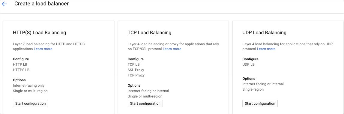
Click CREATE LOAD BALANCER.
-
Under HTTP(S) Load Balancing, click Start configuration.
-
For the Name, enter
pcf-global-pcf. -
Select Backend configuration
- From the drop-down menu, click Backend services, then Create a backend service.
-
Complete the form as follows: *Name:
pcf-http-lb-backend.- Protocol:
HTTP. *Named port:http. - Timeout:
10 seconds. *Under Backends, then New backend, click the Instance group that corresponds to the first zone of the multi-zone instance group you created. For example:pcf-http-lb (us-west1-a). Click Done. - Click Add backend, click the Instance group that corresponds to the second zone of the multi-zone instance group you created. For example:
pcf-http-lb (us-west1-b). Click Done. *Click Add backend, click the Instance group that corresponds to the third zone of the multi-zone instance group you created. For example:pcf-http-lb (us-west1-c). Click Done. - Health check: Click the
pcf-cf-publichealth check that you created. - Cloud CDN: Ensure Cloud CDN is deactivated.
- Protocol:
-
Click Create.
Configure front end
-
Click Host and path rules to populate the default text boxes and a green check mark.
-
Click Frontend configuration, and add the following:
- Name:
pcf-cf-lb-http - Protocol:
HTTP - IP: Perform the following steps:
- Click Create IP address.
- Enter a Name for the new static IP address and an optional description. For example,
pcf-global-pcf. - Click Reserve.
- Port:
80
- Name:
-
Click Add Frontend IP and port and add the following:
Skip this step if you do not have either a self-signed or trusted SSL certificate.
When you configure the tile for your chosen runtime, you are given the opportunity to create a new self-signed certificate. Upon creating a certificate, you can complete the Add Frontend IP and port section.
- Name:
pcf-cf-lb-https - Protocol:
HTTPS - IP address: Click the
pcf-global-pcfaddress you create for the previous Frontend IP and Port. - Port:
443 - Select Create a new certificate. The Create a New Certificate dialog is displayed.
-
In the Name text box, enter a name for the certificate.
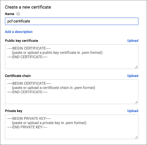
-
In the Public key certificate text box, copy in the contents of your public certificate, or upload your certificate as a .pem file. If the certificate is runtime-generated, copy and paste the generated contents from the runtime’s Certificate text box into the BOSH Director Public key certificate text box.
- In the Certificate chain text box, enter or upload your certificate chain in the .pem format. If you are using a self-signed certificate, such as a TAS for VMs or TKGI-generated certificate, do not enter a value in the Certificate Chain text box.
- In the Private key text box, copy in the contents or upload the .pem file of the private key for the certificate. If the certificate is runtime-generated, copy and paste the generated contents from the runtime’s Private Key text box into the BOSH Director Private key text box.
- Name:
-
Review the completed frontend configuration.
-
Click Review and finalize to verify your configuration.
-
Click Create.
Step 9: Create TCP WebSockets load balancer
The load balancer for tailing logs with WebSockets for Tanzu Operations Manager on GCP operates on TCP port 443.
-
From the GCP console, click Network services, then Load balancing, followed by Create load balancer.
-
Under TCP Load Balancing, click Start configuration.
-
On the Create a load balancer configuration UI, make the following selections:
- Under Internet facing or internal only, click From Internet to my VMs.
- Under Multiple regions or single region, click Single region only.
-
Under Connection termination, click No (TCP).

-
Click Continue.
-
In the New TCP load balancer window, enter
pcf-wss-logsin the Name text box. -
Click Backend configuration to configure the Backend service:
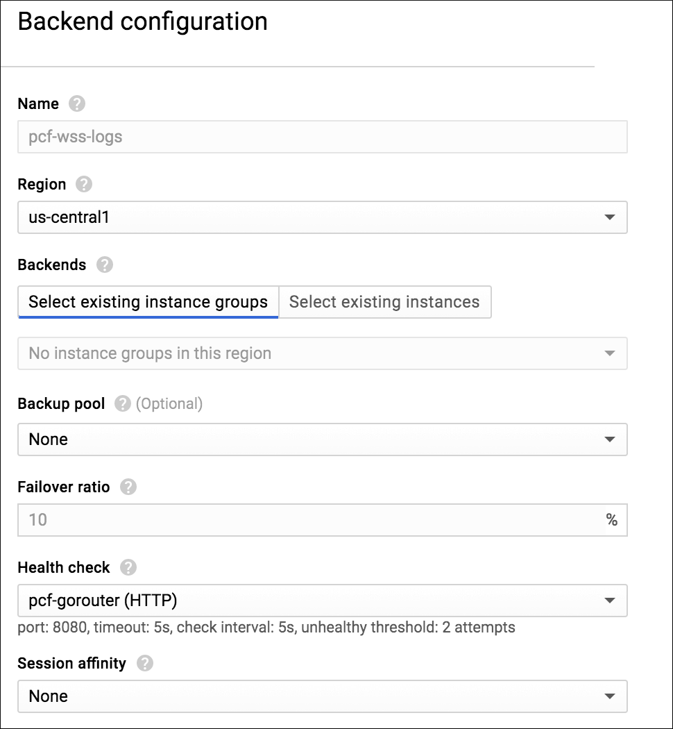
- Region: Click the region you used to create the network in Create a GCP Network with Subnets.
- From the Health check drop-down menu, create a health check with the following details:
- Name:
pcf-gorouter - Port:
8080 - Request path:
/health - Check interval:
30 - Timeout:
5 - Healthy threshold:
10 - Unhealthy threshold:
2The Backend configuration section shows a green check mark.
- Name:
-
Click Frontend configuration to open its configuration window and complete the textb boxes:
- Protocol:
TCP - IP: Perform the following steps:
- Click Create IP address.
- For name Name for the new static IP address and an optional description. For example,
pcf-gorouter-wss. - Click Reserve.
- Port:
443
- Protocol:
-
Click Review and finalize to verify your configuration.
-
Click Create.
Step 10: Create SSH proxy load balancer
-
From the GCP console, click Network services, then Load balancing, followed by Create load balancer.
-
Under TCP Load Balancing, click Start configuration.
-
Under Internet facing or internal only, click From Internet to my VMs.
-
Under Connection termination, click No (TCP).
-
Click Continue.
-
In the New TCP load balancer window, enter
pcf-ssh-proxyin the Name text box. -
Click Backend configuration, and enter the following values:
- Region: Click the region you used to create the network in Create a GCP Network with Subnet.
- Backup pool:
None - Failover ratio:
10% - Health check:
No health check

-
Click Frontend configuration, and add the following:
- Protocol:
TCP - IP: Perform the following steps:
- Click Create IP address.
- Enter a Name for the new static IP address and an optional description. For example,
pcf-ssh-proxy. - Click Reserve.
- Port:
2222
- Protocol:
-
(Optional) Review and finalize your load balancer.
-
Click Create.
Step 11: Create load balancer for TCP router
This step is optional and only required if you enable TCP routing in your deployment.
To create a load balancer for TCP routing in GCP:
-
From the GCP console, click Network services, then Load balancing, followed by Create load balancer.
-
Under TCP Load Balancing, click Start configuration.
-
Under Connection termination, click No (TCP) and click Continue.
-
On the New TCP load balancer pane, enter a unique name for the load balancer in the Name text box. For example,
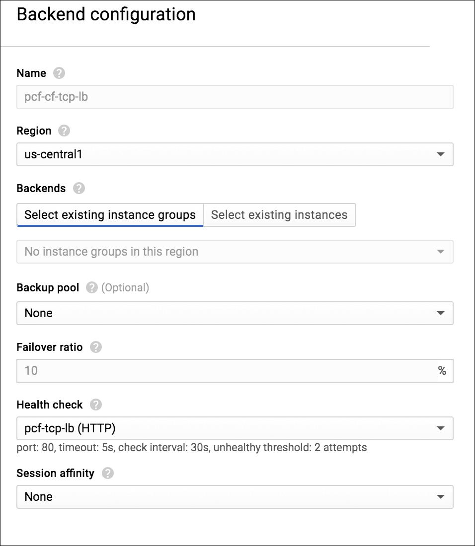
pcf-cf-tcp-lb. -
Click Backend configuration, and enter the following values:
- Region: Click the region you used to create the network in Create a GCP Network with Subnet.
-
From the Health check drop-down menu, create a health check with the following details:
- Name:
pcf-tcp-lb - Port:
80 - Request path:
/health - Check interval:
30 - Timeout:
5 - Healthy threshold:
10 - Unhealthy threshold:
2 -
Click Save and continue.
- Name:
-
Click Frontend configuration, and add the front end IP and port entry as follows:
- Protocol:
TCP - IP: Perform the following steps:
- Click Create IP address.
- Enter a Name for the new static IP address and an optional description. For example,
pcf-cf-tcp-lb. - Click Reserve.
-
Port:
1024-65535
- Protocol:
-
Click Review and finalize to verify your configuration.
-
Click Create.
Step 12: Add DNS records for your load balancers
In this step, you redirect queries for your domain to the IP addresses of your load balancers.
-
Locate the static IP addresses of the load balancers you created in Preparing to deploy Tanzu Operations Manager on GCP:
- An HTTP(S) load balancer named
pcf-global-pcf - A TCP load balancer for WebSockets named
pcf-wss-logs - A TCP load balancer named
pcf-ssh-proxy - A TCP load balancer named
pcf-cf-tcp-lb
You can locate the static IP address of each load balancer by clicking its name under Network services, then Load balancing in the GCP console.
- An HTTP(S) load balancer named
-
Log in to the DNS registrar that hosts your domain. Examples of DNS registrars include Network Solutions, GoDaddy, and Register.com.
-
Create A records with your DNS registrar that map domain names to the public static IP addresses of the load balancers located above:
Create and map this record... To the IP of this load balancer Required \*.sys.MY-DOMAIN
Example:\*.sys.example.compcf-global-pcfYes \*.apps.MY-DOMAIN
Example:\*.apps.example.compcf-global-pcfYes doppler.sys.MY-DOMAIN
Example:doppler.sys.example.compcf-wss-logsYes loggregator.sys.MY-DOMAIN
Example:loggregator.sys.example.compcf-wss-logsYes ssh.sys.MY-DOMAIN
Example:ssh.sys.example.compcf-ssh-proxyYes, to allow SSH access to apps tcp.MY-DOMAIN
Example:tcp.example.compcf-cf-tcp-lbNo, only set up if you have enabled the TCP routing feature -
Save your changes within the web interface of your DNS registrar.
-
Run the following
digcommand to confirm that you created your A record successfully:dig SUBDOMAIN.EXAMPLE-URL.comWhere
SUBDOMAIN.EXAMPLE-URLis the subdomain for your load balancer.You should see the A record that you just created:
;; ANSWER SECTION:
xyz.EXAMPLE.COM.      1767    IN  A 203.0.113.1
Next steps
(Optional) To prepare for deploying either a TAS for VMs or TKGI tile on GCP, you can download the required runtime tile in advance:
- To download TAS for VMs, log in to the Broadcom Support portal, select your desired release version, and download VMware Tanzu Application Service for VMs.
- To download TKGI, log in to the Broadcom Support portal, select your desired release version, and download VMware Tanzu Kubernetes Grid Integrated Edition.
After initiating the tile download, proceed to the next step, Deploying Tanzu Operations Manager on GCP.
