VMware Telco Cloud Platform RAN uses network timing distribution as the preferred method for Precision Time Protocol (PTP) time synchronization. For the RAN to operate effectively, the Radio Unit (RU), Distributed Unit (DU), and Centralized Unit (CU) must be time and phase synchronized. Delayed synchronization can have a negative impact on network applications, leading to low throughput, poor attachment success rate, poor delivery success rate, and so on.
S-Plane Configuration Modes
The Open RAN (O-RAN) Alliance defined the following Synchronization Plane (S-Plane) configuration modes for timing distribution in the RAN infrastructure. These modes establish time synchronization between O-RU and O-DU.
LLS-C1
LLS-C2
LLS-C3
LLS-C4
Telco Cloud Platform RAN supports only LLS-C3 and LLS-C1 configuration modes when using specific hardware. For more information about all these modes, see the O-RAN Control, User, and Synchronization Plane Specification (O-RAN.WG4.CUS.0-R003-v13.00).
LLS-C1 Configuration:
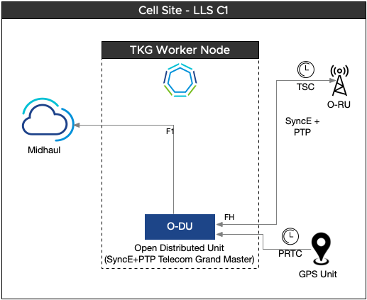
The Link Local Signaling-C1 (LLS-C1) configuration requires point-to-point connection defined between O-DU and O-RU by using the network timing option. LLS-C1 is simple to configure. In cell sites with LLS-C1 configuration, O-DU operates as PTP grandmaster. O-DU derives the time signal typically from an onboard GNSS grandmaster and communicates directly with O-RU for synchronization.
To implement LLS-C1, specific hardware is required. Network Interface Cards (NICs) with onboard GNSS are leveraged to support LLS-C1 deployments. With this LLS-C1 configuration, the grandmaster (GM) functionality is integrated into the O-DU and no longer resides as an external component. VMware Telco Cloud Platform RAN supports LLS-C1 based deployments on Intel E810XXVDA4TGG1 (Westport) and Silicom STS2/STS4 cards.
LLS-C2 Configuration:
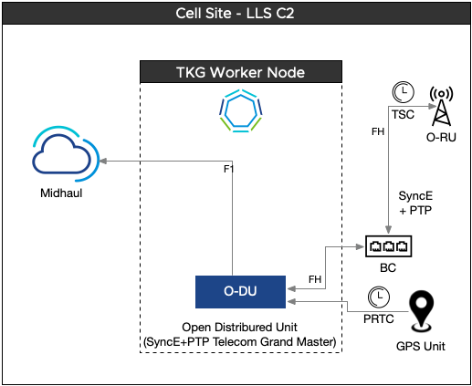
In cell sites with LLS-C2 configuration, the O-DU functions as a PTP Grandmaster, allocating network timing to the RU. One or more PTP-supported switches can be installed between the O-DU and the O-RU.
LLS-C3 Configuration:
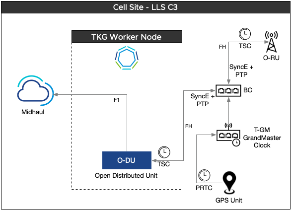
In cell sites with LLS-C3 configuration, network timing distribution is carried out from Primary Reference Time Clock/Telecom Grandmaster (PRTC/T-GM) to O-DU and O-RU. One or more PTP switches are allowed in the Fronthaul network to support network timing distribution.
LLS-C4 Configuration:
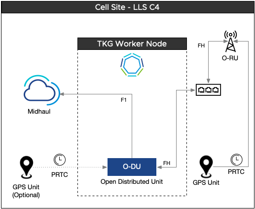
In cell sites with LLS-C4 configuration, PRTC in the form GNSS receiver is used locally to provide timing for the O-RU. PRTC does not depend on the Fronthaul transport network for timing and synchronization. The same or a separate GNSS can be used to provide clocking directly to the O-DU. Clock synchronization is not supported using the direct link between the O-RU and O-DU.
PTP
PTP, defined in accordance with the IEEE 1588 standard, provides an accurate distribution of time and frequency over a packet-based network. A PTP synchronization system comprises both PTP-aware devices and non-PTP-aware devices.
PTP Clocks:
Telecom Grandmaster (T-GM): The primary clock at the beginning of a PTP domain. It is typically located at the core network.
Telecom Boundary Clock (T-BC): A clock that can function both as a Client and a Server. It receives the sync signal from the primary clock, adjusts for any delay, and generates a new primary synchronization signal to pass downstream to the next device.
Telecom Time Slave Clock (T-TSC): The end device that receives the synchronization signal.
Telecom Transparent Clock (T-TC): A clock that timestamps and sends a synchronization packet message to the secondary device. It enables the secondary device to calculate the network delay.
PTP in Passthrough Mode:
VMware Telco Cloud Automation supports PTP in Passthrough mode on XXV710 and E810 cards. To use PTP in Passthrough mode, set the Device Type to NIC when configuring PTP using Infrastructure Designer. For more information, see Infrastructure Requirements Designer in the Telco Cloud Automation User Guide.
For the XXV710 card, you can use any Physical Function (PF) port for PTP.
For the E810 card, you can use only PF0 for PTP.
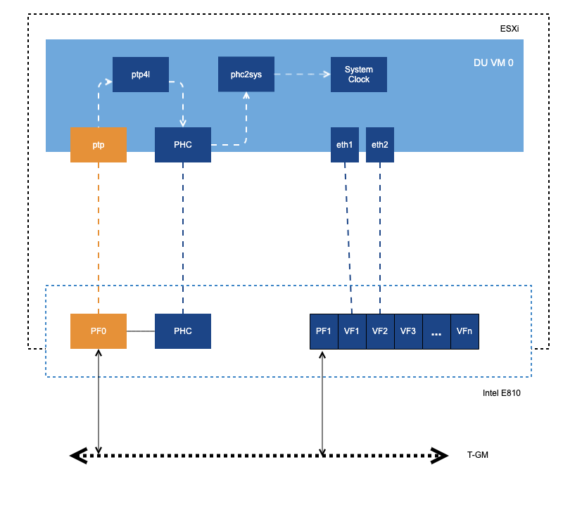
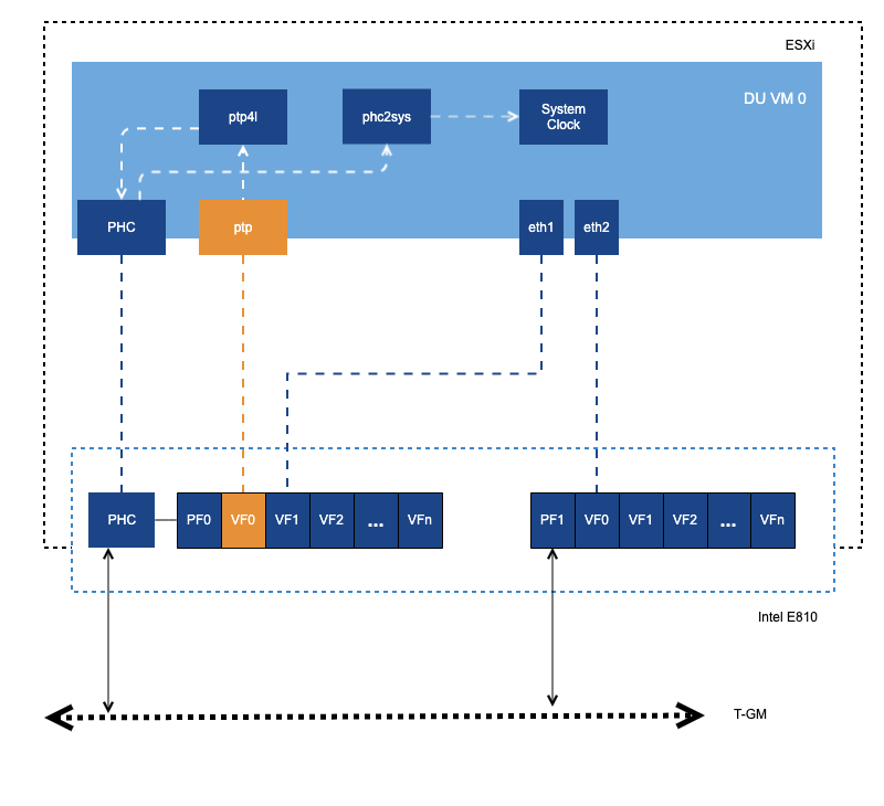
PTP over VF Mode:
VMware Telco Cloud Automation supports PTP over VF only for Intel E810 NICs. You can use any port of the E810 card for PTP over VF.
Resource Requirements for PTP Time Synchronization and Notification
Telco Cloud Platform RAN supports PTP configuration by using VMware PTP Timing Pod and the Systemd service. VMware recommends the use of the PTP timing pod as it guarantees dedicated vCPU resources for timing services. The following tables list the resource requirements for containers used in PTP configuration.
PTP Configuration using Systemd:
CPU |
Memory |
|---|---|
250m |
256Mi |
CPU |
Memory |
|
|---|---|---|
PTP notification container |
250m |
512Mi |
MessageQ container |
250m |
512Mi |
CPU |
Memory |
|---|---|
250m |
256Mi |
CPU |
Memory |
|
|---|---|---|
timing-controller container |
1 dedicated CPU |
256Mi |
PTP notification container |
250m |
512Mi |
MessageQ container |
250m |
512Mi |
Sample values in this section are only for reference purposes.