


In RAN virtualization, the baseband radio functions are moved from custom-built hardware to vendor-agnostic Commercial Off-the-Shelf (COTS) hardware.
In 3GPP R15, the division of the upper and lower sections of the RAN was standardized. The higher-layer split is specified with a well-defined interface (F1) between the Centralized Unit (gNB-CU) and the Distributed Unit (gNB-DU). The CU and its functions, which are similar to the radio, have less stringent processing specifications and are more virtualization-friendly than the DU and its functions. The enhanced Common Public Radio Interface (eCPRI) links the DU to the radio.
The benefits of a fully virtualized or Open-RAN (O-RAN) are as follows:
A single uniform hardware platform can be used across the core, RAN, and edge networks. This simplifies network management while lowering operational and maintenance costs.
The network functions and computing hardware are isolated in a fully virtualized RAN. The network functions of the RAN can be performed on the same hardware, giving the service provider more versatility. The functionality and capacity of a virtualized RAN can be easily implemented where and when it is required, giving it more flexibility.
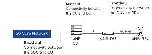
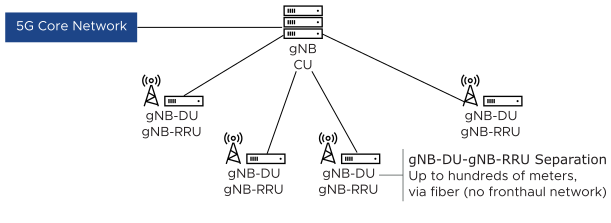
vRAN can be designed in multiple ways. The main interfaces are Fronthaul, Midhaul, and Backhaul. Clocking between the gNB-DU and the gNB-RRU is also significant. The Fronthaul can be logically split into S-Plane, M-Planes, and U-Planes for Clocking, Management, and data traffic.
The main units of the gNodeB are as follows:
Centralized Unit (CU) provides non-real-time processing and access control. It manages higher layer protocols including Radio Resource Control (RRC) from the Control Plane, Service Data Adaptation Protocol (SDAP), and Packed Data Convergence Protocol (PDCP) from the User Plane. The CU is connected between the 5G core network and the DUs. One CU can be connected to multiple DUs.
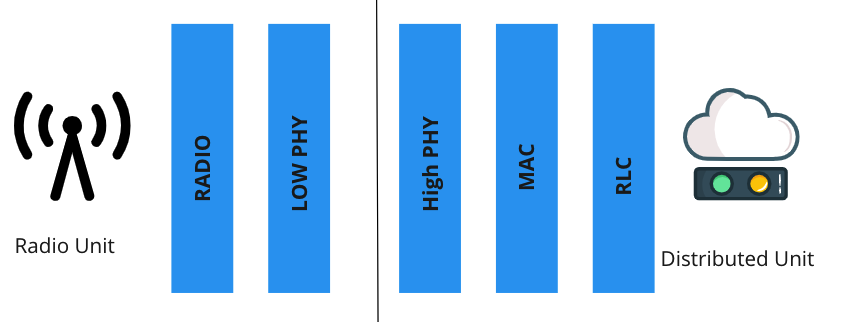
Distributed Unit (DU) provides real-time processing and coordinates lower layer protocols including Physical Layer, Radio Link Control (RLC), and Media Access Control (MAC).
Remote Radio Unit (RRU) does the physical layer transmission and reception, supporting technologies such as Multiple Input Multiple Output (MIMO).
3GPP defined eight functional split options for Fronthaul networks. Options 2 and 7.x are the most commonly adopted Radio Splits.
Option 2: A high-level CU and DU split. The CU handles Service Data Adaptation Protocol (SDAP) or Packet Data Convergence Protocol (PDCP) with Radio Resource Control (RRC) while L2/L1 Ethernet functions reside in the DU. Before the data is sent across the Medium haul network, aggregation and statistical multiplexing of the data are done in the DU. So, the amount of data transmitted across the interface for each radio antenna appliance is reduced.
Option 7.x: A low-level DU and RU split. The DU handles the RRC, PDCP, Radio Link Control (RLC) MAC, and higher Physical (PHY) functions. The RU handles the lower PHY and RF functions. A single DU is typically co-located with multiple RUs, offloading resource-intensive processing from multiple RUs. CU can be centrally located across the WAN, aggregating multiple DUs. Option 7.x lets operators simplify the deployment of the DU and RU, leading to a cost-effective solution and an ideal option for a distributed RAN deployment. Use LLC-C3 for PTP synchronization between the RU and DU.
Mobile operators require the flexibility to choose different splits based on the server hardware and fronthaul availability. Higher-layer functional splits are required for dense urban areas and scenarios, while a low fronthaul bit rate is required for a fronthaul interface.
The 7.2 split model is used commonly for O/V-RAN deployments. It distributes the L1 PHY functions between the RU and the DU, enabling a variable uplink on the F1 interface. It also allows the DU to have more functionality and process multiple sectors and sub-carriers, simplifying the RRU.
vRAN Design Approaches
The different design approaches of vRAN are as follows:
Co-located CU and DU:
A non-centralized approach utilizes the CU and DU functions co-located, with RRU physically separated.
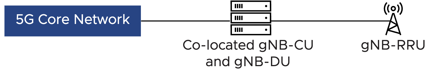
In this model, only fronthaul and backhaul interfaces are required, Fronthaul to the RU and backhaul from the CU.
Centralized Processing:
In the centralized approach, all functional elements of the gNB are physically separated. A single CU is responsible for several DUs. The design requirements of the Next-Generation RAN (NG-RAN) require specific transport network specifications to meet the required distances. This design model requires fronthaul, midhaul, and backhaul connectivity and is often called Centralized-RAN (C-RAN) or a BBU hotel-like model.
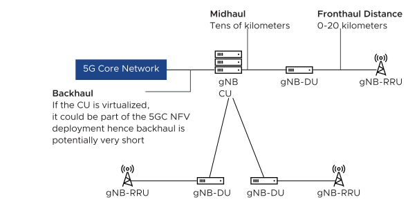
DU and RRU Co-Located(D-RAN):
In this vRAN design, the DU and RRU are co-located such that they are directly connected without a fronthaul transport network. This connection is fiber-based and may span hundreds of meters, supporting scenarios where the DU and RRU are within the same building. This design requires midhaul and backhaul connectivity as shown in the following figure and is often called the Distributed RAN (D-RAN) model.
The centralized processing model introduces several potential advantages:
Cost Reduction: Centralized processing capability reduces the cost of the DU function.
Energy Efficiency, Power and Cost Reduction: Reducing the hardware in the cell site, reduces the power consumption and air conditioning of that site. The cost saving can be significant when you deploy tens or hundreds of cell sites.
Flexibility: Flexible hardware deployment leads to a highly scalable and cost-effective RAN solution. Also, the functional split of the protocol stack impacts the transport network.
Higher Performance: Better performance is achieved through improved load management, cell coordination, and the future deployment of Radio interference mitigation algorithms.
Improved offload and content delivery: Aggregation of processing at the CU provides an optimal place in the network for data offload and MEC application delivery.
The Distributed model (DU/RU Co-Located) also introduces several advantages:
Transport Costs: This model avoids unnecessary transport (backhaul) of the RU-DU fronthaul interface. This can be significant in terms of bandwidth requirements of the fronthaul interface.
Proximity: Allows the DU to be placed closer to the RU and introduces support for additional clocking methodologies such as LLS-C1.
Most RAN networks are comprised of DU nodes at the remote-cell sites, co-located with the RRU, and a smaller portion of the centralized model where the DUs are collected at a far/near-edge location. This allows maximum flexibility in terms of workload distribution and edge functionality in the future.
C-RAN Design Considerations
The Centralized RAN approach consolidates multiple ESXi hosts in a single place, aligning to the concept of a near-edge or far-edge design. The following considerations are applicable for designing a C-RAN workload cluster.
Do not use vSAN as the main datastore. The extreme real-time nature of the DU may be impacted by vSAN rebuilds or other events.
The C-RAN TKG deployment can use a single vSphere cluster as the target endpoint. This allows the creation of a single node pool of TKG worker nodes and the provisioning of one-time Dynamic Infrastructure for all worker nodes in the cluster.
PTP Time Synchronization
RAN maintains network timing distribution as the preferred method for PTP time synchronization. For the RAN to operate effectively, the RU, DU, and CU must be time and phase synchronized. The delayed synchronization can have a negative impact on network applications. For example, low throughput, poor attachment success rate, and poor delivery success rate.
The accuracy of time synchronization depends mostly on the implementation of network connectivity and PTP protocol distribution. For example, the timestamp near interfaces and the number of hops. The O- RAN.WG4 Fronthaul networks define the following synchronization topologies for telco deployment:
LLS-C1 Configuration
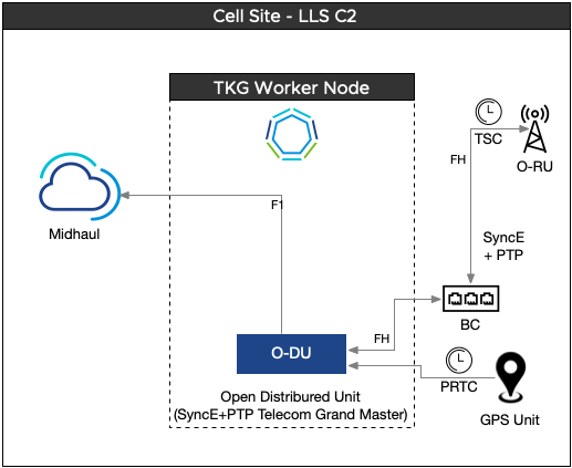
LLS-C2 Configuration
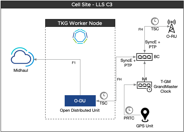
LLS-C3 Configuration
LLS-C4 Configuration
Consider PTP time synchronization based on these designs. However, Telco Cloud Platform RAN supports LLS-C3 configuration and LLS-C1 when using specific hardware.
LLS-C1 Architecture
This configuration is based on the point-to-point connection between DU and RU by using the network timing option. LLS-C1 is simple to configure. In this configuration, DU operates as PTP grandmaster. The O-DU derives the time signal from (typically an onboard GNSS) Grandmaster and communicates directly with the O-RU to synchronize it.
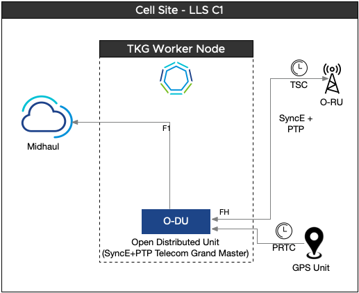
The architecture for LLS-C1 requires the O-RU units to be physically homed to the ESXi server.
To implement LLS-C1, specific hardware is required. Network Interface Cards with onboard GNSS are leveraged to support LLS-C1 deployments. With this configuration, the GM functionality is integrated into the server and no longer resides as an external component.
LLS-C2 Configuration
In this configuration, the O-DU acts as PTP Grandmaster allocating network timing towards the RU. One or more PTP-supported switches can be installed between the O-DU and the O-RU.
LLS-C3 Configuration
In this configuration, the PTP Grandmaster performs network time-sharing between the O-DU and O-RU at Cell Sites. One or more PTP switches are allowed in the Fronthaul network to support network time-sharing. This architecture is widely adopted by introducing the PTP Grandmaster and PTP Switch, which provide the ideal solution for network time-sharing.
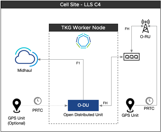
LLS-C4 Configuration
In this configuration, PRTC (usually the GNSS receiver) is used locally to provide timing for the O-RU. PRTC does not depend on the Fronthaul transport network for timing and synchronization. The same or a separate GNSS can be used to provide clocking directly to the O-DU. Clock-sync is not supported using the direct link between the O-RU and O-DU.
Synchronous Ethernet Support
Synchronous Ethernet leverages the OSI layer 1 (Physical layer) to pass timing between nodes, similar to the traditional method used in SDH / TDM based circuits.
