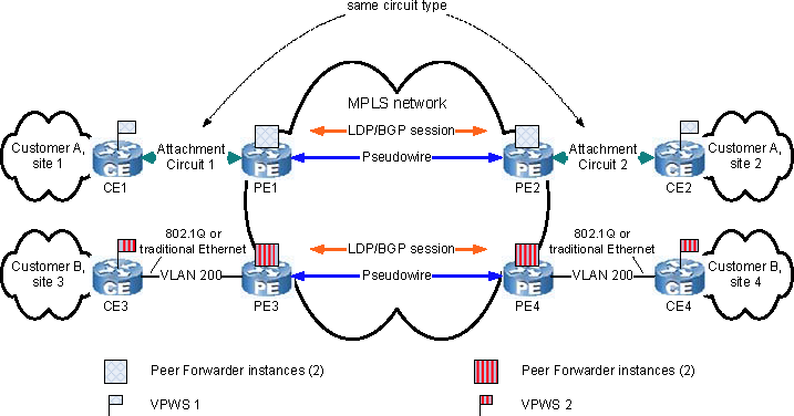
A VPWS is a provider-provisioned point-to-point service that connects two CE devices. Using VPWS to connect customer sites over an MPLS network identifies the basic components of a VPWS.

A VPWS consists of two Attachment Circuits, two Forwarders, and a pseudowire. The pseudowire emulates a Layer 2 circuit.
In Figure 37, the “Attachment Circuit” pair for VPWS 1 represents one of many circuit types that have been defined for encapsulating different Layer 2 protocols in MPLS packets. One such circuit type, Ethernet VLAN, is shown in VPWS 2.
The most popular proposal for VPWS is the Martini draft proposal, which defines 10 circuit types and recommends LDP signaling. Other VPWS proposals support the 10 circuit types but recommend BGP signaling.
LDP or BGP signaling is used by the PE pair in a VPWS to construct, advertise, maintain, and delete label bindings for the pseudowire. The PEs must agree on the meaning of the labels that the PEs will use to forward traffic to each other.
In an LDP-signaled VPWS, the pseudowire is identified by a VC ID. In a BGP-signaled VPWS, the pseudowire is identified by a combination of an incoming VC ID and an outgoing VC ID.
Note that in an LDP-signaled VPWS, VC ID is an identifier for both virtual circuits of a pseudowire. In a BGP-signaled VPWS, incoming VC ID is an identifier for one virtual circuit of a pseudowire, and outgoing VC ID is an identifier for the other virtual circuit.