The three figures, BGP Connectivity map launched for an AutonomousSystem objectthrough BGP Connectivity map launched for a BGPSession object, show the initial layout of a BGP Connectivity map launched for an AutonomousSystem object, a BGPService object, and a BGPSession object, respectively. No physical connectivity details are included in the BGP Connectivity map.
The layout of a BGP Connectivity map depends on the object that you select to launch the map. The launching object for the map, called the focal object, is surrounded by a box unless the focal object is displayed in a container, or is a BGPSession object. The container identifies which devices and BGP services are part of an autonomous system.
BGP Connectivity map launched for an AutonomousSystem objectis an example of a BGP Connectivity map that has an AutonomousSystem focal object. The map shows the autonomous system container, the member devices within the container, and the BGP sessions (solid green lines) that connect the member devices. Each member device is running a BGP service.
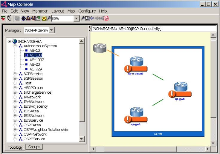
Figure 2-9also shows a stub adjacency, which is represented as a solid yellow line connected to a gray router icon. Yellow indicates that the stub adjacency is affected by an abnormal condition. The device that is represented by the gray router icon is not present in the repository of Network Protocol Manager for BGP.
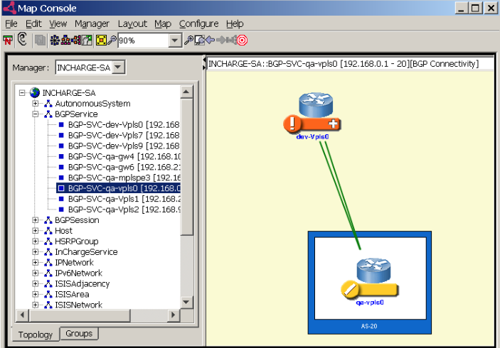
BGP Connectivity map launched for a BGPService objectis an example of a BGP Connectivity map that has a BGPService focal object. The map shows the selected BGP service and its hosting device, along with its neighboring BGP service and that service™s hosting device. Because the selected BGP service is displayed in a container, it is not surrounded by a box.
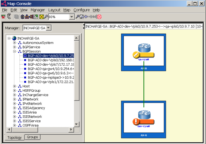
BGP Connectivity map launched for a BGPSession objectis an example of a BGP Connectivity map that has a BGPSession focal object. The map shows the selected BGP session, which is represented as a solid green line, between the two devices that are running neighboring BGP services. Green indicates that the BGP session is healthy.