


When you use ESXi with iSCSI SAN, follow recommendations that VMware offers to avoid problems.
Check with your storage representative if your storage system supports Storage API - Array Integration hardware acceleration features. If it does, refer to your vendor documentation to enable hardware acceleration support on the storage system side. For more information, see Storage Hardware Acceleration in vSphere.
Preventing iSCSI SAN Problems
When using ESXi with a SAN, you must follow specific guidelines to avoid SAN problems.
Observe the following tips:
- Place only one VMFS datastore on each LUN.
- Do not change the path policy the system sets for you unless you understand the implications of making such a change.
- Document everything. Include information about configuration, access control, storage, switch, server and iSCSI HBA configuration, software and firmware versions, and storage cable plan.
- Plan for failure:
- Make several copies of your topology maps. For each element, consider what happens to your SAN if the element fails.
- Cross off different links, switches, HBAs, and other elements to ensure that you did not miss a critical failure point in your design.
- Ensure that the iSCSI HBAs are installed in the correct slots in the ESXi host, based on slot and bus speed. Balance PCI bus load among the available buses in the server.
- Become familiar with the various monitor points in your storage network, at all visibility points, including ESXi performance charts, Ethernet switch statistics, and storage performance statistics.
- Change LUN IDs only when VMFS datastores deployed on the LUNs have no running virtual machines. If you change the ID, virtual machines running on the VMFS datastore might fail.
After you change the ID of the LUN, you must rescan your storage to reset the ID on your host. For information on using the rescan, see Rescan Operations for ESXi Storage.
- If you change the default iSCSI name of your iSCSI adapter, make sure that the name you enter is worldwide unique and properly formatted. To avoid storage access problems, never assign the same iSCSI name to different adapters, even on different hosts.
Optimizing iSCSI SAN Storage Performance
Several factors contribute to optimizing a typical SAN environment.
If the network environment is properly configured, the iSCSI components provide adequate throughput and low enough latency for iSCSI initiators and targets. If the network is congested and links, switches or routers are saturated, iSCSI performance suffers and might not be adequate for ESXi environments.
Storage System Performance
Storage system performance is one of the major factors contributing to the performance of the entire iSCSI environment.
If issues occur with storage system performance, consult your storage system vendor’s documentation for any relevant information.
When you assign LUNs, remember that you can access each shared LUN through a number of hosts, and that a number of virtual machines can run on each host. One LUN used by the ESXi host can service I/O from many different applications running on different operating systems. Because of this diverse workload, the RAID group that contains the ESXi LUNs should not include LUNs that other hosts use that are not running ESXi for I/O intensive applications.
Enable read caching and write caching.
Load balancing is the process of spreading server I/O requests across all available SPs and their associated host server paths. The goal is to optimize performance in terms of throughput (I/O per second, megabytes per second, or response times).
SAN storage systems require continual redesign and tuning to ensure that I/O is load balanced across all storage system paths. To meet this requirement, distribute the paths to the LUNs among all the SPs to provide optimal load balancing. Close monitoring indicates when it is necessary to manually rebalance the LUN distribution.
Tuning statically balanced storage systems is a matter of monitoring the specific performance statistics (such as I/O operations per second, blocks per second, and response time) and distributing the LUN workload to spread the workload across all the SPs.
Server Performance with iSCSI
To ensure optimal ESXi host performance, consider several factors.
Each server application must have access to its designated storage with the following conditions:
- High I/O rate (number of I/O operations per second)
- High throughput (megabytes per second)
- Minimal latency (response times)
Because each application has different requirements, you can meet these goals by selecting an appropriate RAID group on the storage system.
To achieve performance goals, follow these guidelines:
- Place each LUN on a RAID group that provides the necessary performance levels. Monitor the activities and resource use of other LUNS in the assigned RAID group. A high-performance RAID group that has too many applications doing I/O to it might not meet performance goals required by an application running on the ESXi host.
- To achieve maximum throughput for all the applications on the host during the peak period, install enough network adapters or iSCSI hardware adapters. I/O spread across multiple ports provides faster throughput and less latency for each application.
- To provide redundancy for software iSCSI, make sure that the initiator is connected to all network adapters used for iSCSI connectivity.
- When allocating LUNs or RAID groups for ESXi systems, remember that multiple operating systems use and share that resource. The LUN performance required by the ESXi host might be much higher than when you use regular physical machines. For example, if you expect to run four I/O intensive applications, allocate four times the performance capacity for the ESXi LUNs.
- When you use multiple ESXi systems with vCenter Server, the storage performance requirements increase.
- The number of outstanding I/Os needed by applications running on an ESXi system must match the number of I/Os the SAN can handle.
Network Performance
A typical SAN consists of a collection of computers connected to a collection of storage systems through a network of switches. Several computers often access the same storage.
The following graphic shows several computer systems connected to a storage system through an Ethernet switch. In this configuration, each system is connected through a single Ethernet link to the switch. The switch is connected to the storage system through a single Ethernet link.
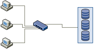
When systems read data from storage, the storage responds with sending enough data to fill the link between the storage systems and the Ethernet switch. It is unlikely that any single system or virtual machine gets full use of the network speed. However, this situation can be expected when many systems share one storage device.
When writing data to storage, multiple systems or virtual machines might attempt to fill their links. As a result, the switch between the systems and the storage system might drop network packets. The data drop might occur because the switch has more traffic to send to the storage system than a single link can carry. The amount of data the switch can transmit is limited by the speed of the link between it and the storage system.
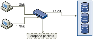
Recovering from dropped network packets results in large performance degradation. In addition to time spent determining that data was dropped, the retransmission uses network bandwidth that can otherwise be used for current transactions.
iSCSI traffic is carried on the network by the Transmission Control Protocol (TCP). TCP is a reliable transmission protocol that ensures that dropped packets are retried and eventually reach their destination. TCP is designed to recover from dropped packets and retransmits them quickly and seamlessly. However, when the switch discards packets with any regularity, network throughput suffers. The network becomes congested with requests to resend data and with the resent packets. Less data is transferred than in a network without congestion.
Most Ethernet switches can buffer, or store, data. This technique gives every device attempting to send data an equal chance to get to the destination. The ability to buffer some transmissions, combined with many systems limiting the number of outstanding commands, reduces transmissions to small bursts. The bursts from several systems can be sent to a storage system in turn.
If the transactions are large and multiple servers are sending data through a single switch port, an ability to buffer can be exceeded. In this case, the switch drops the data it cannot send, and the storage system must request a retransmission of the dropped packet. For example, if an Ethernet switch can buffer 32 KB, but the server sends 256 KB to the storage device, some of the data is dropped.
Most managed switches provide information on dropped packets, similar to the following:
*: interface is up
IHQ: pkts in input hold queue     IQD: pkts dropped from input queue
OHQ: pkts in output hold queue    OQD: pkts dropped from output queue
RXBS: rx rate (bits/sec)          RXPS: rx rate (pkts/sec)
TXBS: tx rate (bits/sec)          TXPS: tx rate (pkts/sec)
TRTL: throttle count
| Interface | IHQ | IQD | OHQ | OQD | RXBS | RXPS | TXBS | TXPS | TRTL |
|---|---|---|---|---|---|---|---|---|---|
| * GigabitEthernet0/1 | 3 | 9922 | 0 | 0 | 476303000 | 62273 | 477840000 | 63677 | 0 |
In this example from a Cisco switch, the bandwidth used is 476303000 bits/second, which is less than half of wire speed. The port is buffering incoming packets, but has dropped several packets. The final line of this interface summary indicates that this port has already dropped almost 10,000 inbound packets in the IQD column.
Configuration changes to avoid this problem involve making sure several input Ethernet links are not funneled into one output link, resulting in an oversubscribed link. When several links transmitting near capacity are switched to a smaller number of links, oversubscription becomes possible.
Generally, applications or systems that write much data to storage must avoid sharing Ethernet links to a storage device. These types of applications perform best with multiple connections to storage devices.
Multiple Connections from Switch to Storage shows multiple connections from the switch to the storage.

Using VLANs or VPNs does not provide a suitable solution to the problem of link oversubscription in shared configurations. VLANs and other virtual partitioning of a network provide a way of logically designing a network. However, they do not change the physical capabilities of links and trunks between switches. When storage traffic and other network traffic share physical connections, oversubscription and lost packets might become possible. The same is true of VLANs that share interswitch trunks. Performance design for a SAN must consider the physical limitations of the network, not logical allocations.
Checking Ethernet Switch Statistics
Many Ethernet switches provide different methods for monitoring switch health.
Switches that have ports operating near maximum throughput much of the time do not provide optimum performance. If you have ports in your iSCSI SAN running near the maximum, reduce the load. If the port is connected to an ESXi system or iSCSI storage, you can reduce the load by using manual load balancing.
If the port is connected between multiple switches or routers, consider installing additional links between these components to handle more load. Ethernet switches also commonly provide information about transmission errors, queued packets, and dropped Ethernet packets. If the switch regularly reports any of these conditions on ports being used for iSCSI traffic, performance of the iSCSI SAN will be poor.
