


A Compute Profile contains the compute, storage, and network settings that HCX uses on this site to deploy the Interconnect-dedicated virtual appliances when a Service Mesh is added.
Create a Compute Profile in the Multi-Site Service Mesh interface in both the source and the destination HCX environments using the planned configuration options for each site, respectively.
Prerequisites
Install and configure HCX Manager.
To obtain the optimum system usage, assign resource configurations based on HCX deployment considerations.
Use the planned configurations collected using the checklist described in Getting Started with VMware HCX.
Procedure
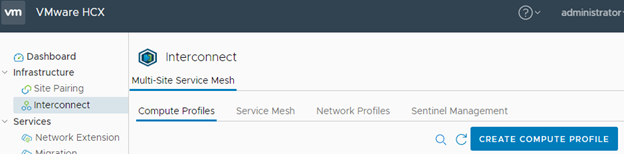
- Click Create Compute Profile.
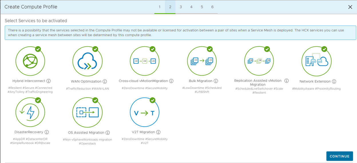
- Select the HCX services to be activated. Click Continue.
Note:
Premium services require the HCX Enterprise license.
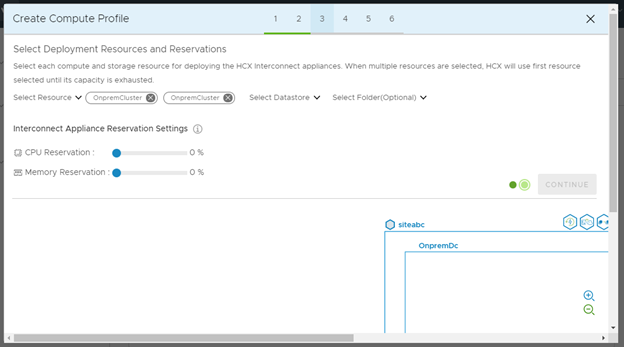
- Make your resource, and resource reservation selections.
- From the Select Resource drop-down menu, and select each cluster or resource pool to be used when deploying HCX Interconnect appliances.
Note: For HCX WAN-OPT appliance deployment in NSX-T enabled environments, NSX-T Overlay Transport Zone must be associated to all hosts that are part of the deployment cluster. This should be done in addition to the NSX-T Overlay or NSX-T VLAN network extension configuration part of Network Containers section.
- From the Select Datastore drop-down menu, and select the datastore to be used when deploying HCX Interconnect appliances.
When multiple compute resources or datastores are selected, HCX uses the first selection until its capacity is exhausted.
- (Optional) From the Select Folder drop-down menu, and specify a folder in which to deploy the HCX appliances.
- Using the slide bar, select the amount of CPU and memory to reserve for HCX operations.
As a best practice, set the CPU and memory reservation to 100 percent.
For example, setting Memory Reservation to 100 percent ensures that all of the memory allocated for HCX appliances is always available for HCX operations.
- From the Select Resource drop-down menu, and select each cluster or resource pool to be used when deploying HCX Interconnect appliances.
- Select the Management Network Profile:
- Click the Select Management Network Profile drop-down menu.
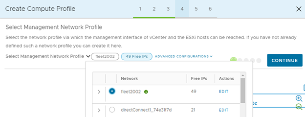
- Select an existing Network Profile or click Create Network Profile to create it.
Reference the Creating a Network Profile topic for more details.
Note:Networks identified with an information icon have been suggested for use with this type of network in the Network Profile. This is only a suggestion, and you can select other networks for this traffic type.
- Expand the selected Management Network Profile to view its details and free IP Addresses. Click Close when done reviewing.
- Click Continue.
- Click the Select Management Network Profile drop-down menu.
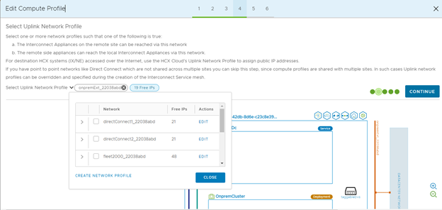
- Select the Uplink Network Profile:
The Network Profile previously selected for another function, like Management can also be assigned as the Uplink Network Profile.
Multiple Network Profiles can be selected.
- Click the Select Uplink Network Profile drop-down menu.
- Select one or more existing Network Profile, or click Create Network Profile to create it.
Reference the Creating a Network Profile topic for more details.
- Expand the selected Uplink Network Profile to view its details and free IP Addresses. Click Close when done reviewing.
- Click Continue.
HCX Manager now updates the topology view to depict the configured Network Profile. As shown in the diagram, the Compute Profile configuration tool displays a symbolic map of the network links between the Interconnect appliance virtual machines to be deployed for the selected Uplink network.
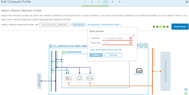
- Select the vMotion Network Profile:
- Click the Select vMotion Network Profile drop-down menu.
- Select an existing Network Profile or click Create Network Profile to create it.
Reference the Creating a Network Profile topic for more details.
- Expand the selected vMotion Network Profile to view its details and free IP Addresses. Click Close when done reviewing.
- Click Continue.
The Network Profile tool now displays a topology view that shows how the selected vMotion Network connects the HCX Interconnect appliances assigned to the profile.
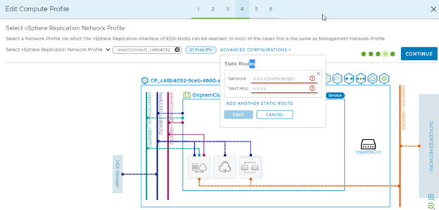
- Select the vSphere Replication Network Profile:
Assigning a vSphere Replication Network Profile is useful when there is a VMkernel interface for the network traffic that is exclusive to vSphere Replication operations. If the Management Network Profile is used for Replication operations, click Continue to skip this step.
- Click the Select vSphere Replication Network Profile drop-down menu.
- Select an existing Network Profile or click Create Network Profile to create it.
Reference the Creating a Network Profile topic for more details.
- Expand the selected vSphere Replication Network Profile to view its details and free IP Addresses. Click Close when done reviewing.
- Click Continue.
Results
A Compute Profile is created, and can be used when creating a service mesh.
What to do next
Once there are valid Compute Profiles in the source and destination environments, use the HCX Manager UI at the source site to create the Interconnect Service Mesh.
To edit an existing Compute Profile, navigate to the specific Compute profile, and click Edit.
