A transport zone controls to which hosts a logical switch can reach. It can span one or more vSphere clusters. Transport zones dictate which clusters and, therefore, which VMs can participate in the use of a particular network. In a cross-vCenter NSX environment you can create a universal transport zone, which can include clusters from any vCenter in the environment. You can create only one universal transport zone.
An NSX Data Center for vSphere environment can contain one or more transport zones based on your requirements. A host cluster can belong to multiple transport zones. A logical switch can belong to only one transport zone.
NSX Data Center for vSphere does not allow connection of VMs that are in different transport zones. The span of a logical switch is limited to a transport zone, so virtual machines in different transport zones cannot be on the same Layer 2 network. A distributed logical router cannot connect to logical switches that are in different transport zones. After you connect the first logical switch, the selection of further logical switches is limited to those that are in the same transport zone.
- If a cluster requires Layer 3 connectivity, the cluster must be in a transport zone that also contains an edge cluster, meaning a cluster that has Layer 3 edge devices (distributed logical routers and edge services gateways).
- Suppose you have two clusters, one for web services and another for application services. To have VXLAN connectivity between the VMs in these two clusters, both of the clusters must be included in the transport zone.
- Keep in mind that all logical switches included in the transport zone will be available and visible to all VMs within the clusters that are included in the transport zone. If a cluster includes secured environments, you might not want to make it available to VMs in other clusters. Instead, you can place your secure cluster in a more isolated transport zone.
- The span of the vSphere distributed switch (VDS or DVS) should match the transport zone span. When creating transport zones in multi-cluster VDS configurations, make sure all clusters in the selected VDS are included in the transport zone. This is to ensure that the DLR is available on all clusters where VDS dvPortgroups are available.
The following diagram shows a transport zone correctly aligned to the VDS boundary.

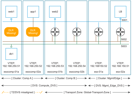
If you do not follow this best practice, keep in mind that if a VDS spans more than one host cluster and the transport zone includes only one (or a subset) of these clusters, any logical switch included within this transport zone can access VMs within all clusters spanned by the VDS. In other words, the transport zone will not be able to constrain the logical switch span to a subset of the clusters. If this logical switch is later connected to a DLR, you must ensure that the router instances are created only in the cluster included in the transport zone to avoid any Layer 3 issues.
For example, when a transport zone is not aligned to the VDS boundary, the scope of the logical switches (5001, 5002 and 5003) and the DLR instances that these logical switches are connected to becomes disjointed, causing VMs in cluster Comp A to have no access to the DLR logical interfaces (LIFs).