


Describes how to configure a Non SD-WAN Destination of type Cisco ISR in SD-WAN Orchestrator.
Procedure
- From the navigation panel in the SD-WAN Orchestrator, go to Configure > Network Services.
The Services screen appears.
- In the Non SD-WAN Destinations via Gateway area, click the New button.
The New Non SD-WAN Destinations via Gateway dialog box appears.
- In the Name text box, enter the name for the Non SD-WAN Destination.
- From the Type drop-down menu, select Cisco ISR.
- Enter the IP address for the Primary VPN Gateway, and click Next.
A Non SD-WAN Destination of type Cisco ISR is created and a dialog box for your Non SD-WAN Destination appears.
- To configure tunnel settings for the Non SD-WAN Destination’s Primary VPN Gateway, click the Advanced button.
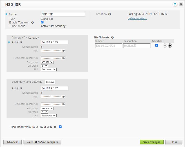
- In the Primary VPN Gateway area, you can configure the following tunnel settings:
Field Description Tunnel Mode Active-Hot-Standby is supported on the SD-WAN Gateway. Active/Hot-Standby automatically displays indicating that if the Active tunnel goes down, the Standby (Hot-Standby) tunnel takes over and becomes the Active tunnel. PSK The Pre-Shared Key (PSK), which is the security key for authentication across the tunnel. The Orchestrator generates a PSK by default. If you want to use your own PSK or password then you can enter it in the text box. Encryption Select either AES 128 or AES 256 as the AES algorithms key size to encrypt data. The default value is AES 128. DH Group Select the Diffie-Hellman (DH) Group algorithm to be used when exchanging a pre-shared key. The DH Group sets the strength of the algorithm in bits. The supported DH Groups are 2, 5, and 14. It is recommended to use DH Group 14. PFS Select the Perfect Forward Secrecy (PFS) level for additional security. The supported PFS levels are 2 and 5. The default value is deactivated. - If you want to create a Secondary VPN Gateway for this site, then click the Add button next to Secondary VPN Gateway. In the pop-up window, enter the IP address of the Secondary VPN Gateway and click Save Changes.
The Secondary VPN Gateway will be created immediately for this site and will provision a VMware SD-WAN VPN tunnel to this Gateway.
Note:For Cisco ISR Non SD-WAN Destination, by default, the local authentication ID value used is SD-WAN Gateway Interface Local IP.
- Select the Redundant VeloCloud Cloud VPN check box to add redundant tunnels for each VPN Gateway.
Any changes made to Encryption, DH Group, or PFS of Primary VPN Gateway will also be applied to the redundant VPN tunnels, if configured. After modifying the tunnel settings of the Primary VPN Gateway, save the changes and then click View IKE/IPsec Template to view the updated tunnel configuration.
- Click the Update location link to set the location for the configured Non SD-WAN Destination. The latitude and longitude details are used to determine the best SD-WAN Edge or SD-WAN Gateway to connect to in the network.
- Under Site Subnets, add subnets for the Non SD-WAN Destination by clicking the + button.
Note: For Cisco ISR, Site Subnets are mandatory to be configured.
- Check the Enable Tunnel(s) check box once you are ready to initiate the tunnel from the SD-WAN Gateway to the Cisco ISR VPN Gateways.
- Click Save Changes.
- Assign the newly created Non SD-WAN Site Network Service to a Profile by navigating to Configure >Profiles in the SD-WAN Orchestrator. See Configure a Tunnel Between a Branch and a Non SD-WAN Destinations via Gateway.
- Return to the Non SD-WAN Destinations via Gateway area in the SD-WAN Orchestrator by going to Configure > Network Services.
- In the Non SD-WAN Destinations via Gateway area, scroll to the name of your Non SD-WAN Site, and then click the Edit link in the BGP column.
- Configure the BGP based on the Cisco ISR values for the following mandatory fields: Local ASN, Tunnel Type, Neighbor IP, and Local IP (from the Advanced Options section). Refer to the Cisco documentation if needed. For more information, see Configure BGP over IPsec from Gateways.
Note: The VTI IP (private IP) assigned by the SD-WAN Orchestrator can be used for peer ship in Single-Hop BGP.
- Click OK to save your changes.
- In the Non SD-WAN Destinations via Gateway area, click the Edit link in the BFD column for a Non SD-WAN Destination, to configure the BFD settings. For more information, see Configure BFD for Gateways.
