


Device Settings allows you configure the Interface Settings for one or more Edge models in a profile.
Depending on the Edge Model, each interface can be a Switch Port (LAN) interface or a Routed (WAN) Interface. Depending on the Branch Model, a connection port is a dedicated LAN or WAN port, or ports can be configured to be either a LAN or WAN port. Branch ports can be Ethernet or SFP ports. Some Edge models may also support wireless LAN interfaces.
It is assumed that a single public WAN link is attached to a single interface that only serves WAN traffic. If no WAN link is configured for a routed interface that is WAN capable, it is assumed that a single public WAN link should be automatically discovered. If one is discovered, it will be reported to the SD-WAN Orchestrator. This auto-discovered WAN link can then be modified via the SD-WAN Orchestrator and the new configuration pushed back to the branch.
- If the routed Interface is activated with the WAN overlay and attached with a WAN link, then the interface will be available for all Segments.
- If an interface is configured as PPPoE, it will only support a single auto-discovered WAN link. Additional links cannot be assigned to the interface.
If the link should not or cannot be auto-discovered, it must be explicitly configured. There are multiple supported configurations in which auto-discovery will not be possible, including:
- Private WAN links
- Multiple WAN links on a single interface. Example: A Datacenter Hub with 2 MPLS connections
- A single WAN link reachable over multiple interfaces. Example: for an active-active HA topology
Links that are auto-discovered are always public links. User-defined links can be public or private, and will have different configuration options based on which type is selected.
Public WAN Links
Public WAN links are any traditional link providing access to the public internet such as Cable, DSL, etc. No peer configuration is required for public WAN links. They will automatically connect to the SD-WAN Gateway, which will handle the dissemination of information needed for peer connectivity.
Private (MPLS) WAN Links
Private WAN links belong to a private network and can only connect to other WAN links within the same private network. Because there can be multiple MPLS networks, within a single enterprise, for example, the user must identify which links belong to which network. The SD-WAN Gateway will use this information to distribute connectivity information for the WAN links.
You may choose to treat MPLS links as a single link. However, to differentiate between different MPLS classes of service, multiple WAN links can be defined that map to different MPLS classes of service by assigning each WAN link a different DSCP tag.
Additionally, you may decide to define a static SLA for a private WAN link. This will eliminate the need for peers to exchange path statistics and reduce the bandwidth consumption on a link. Since probe interval influences how quickly the device can fail over, it’s not clear whether a static SLA definition should reduce the probe interval automatically.
Device Settings
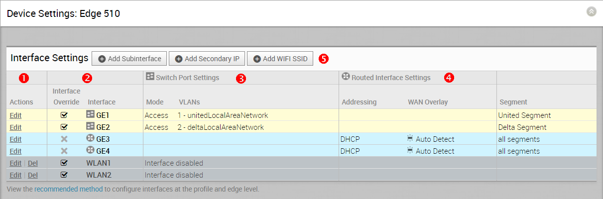
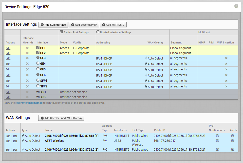
The following screen captures illustrate the top-level user interface for the SD-WAN Edge 500, SD-WAN Edge 1000, and introducing SD-WAN Edge 610 for the 3.4 release. The following table describes the major features.
| |
Actions you can perform on the network interface, such as Edit or Delete. |
| |
The Interface name. This name matches the Edge port label on the Edge device or is predetermined for wireless LANs. |
| |
The list of Switch Ports with a summary of some of their settings (such as Access or Trunk mode and the VLANs for the interface). Switch Ports are highlighted with a light, yellow background. |
| |
The list of Routed Interfaces with a summary of their settings (such as the addressing type and if the interface was auto-detected or has an Auto Detected or User Defined WAN overlay). Routed Interfaces are highlighted with a light, blue background. |
| |
The list of Wireless Interfaces (if available on the Edge device). You can add additional wireless networks by clicking the Add Wi-Fi SSID button. Wireless Interfaces are highlighted with a light, gray background. |
| |
|
Edges Without Wifi Modules
VMware supports Edge models 510, 610, 620, 640, and 680 without WiFi modules for the following releases: 3.4.6, 4.2.2, 4.3.0, 4.3.1, and 4.5.0. For specific model names, see table below. The Edge 6X0 series device and 510 Edge device are shipped with default images, but the working image is typically downloaded from the SD-WAN Orchestrator upon activation.
| Marketing Name | Hardware Model | Hardware Part Number |
|---|---|---|
| Edge 510N | Edge 510 | Edge 510-NW |
| Edge 610N | E42W | Edge 610N |
| Edge 610-LTE | E42W | Edge 610LTE-RW, Edge 610LTE-AM |
| Edge 620N | E42W | Edge 620N |
| Edge 640N | E42W | Edge 640N |
| Edge 680N | E42W | Edge 680N |
Edge 610-LTE
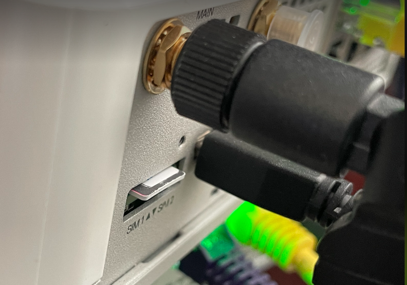
The Edge 610-LTE is an extension of the Edge 610 with an integrated CAT12 EM75xx Sierra Wireless (SWI) modem. The 610-LTE device supports all the features that the 510-LTE offers, with an additional power of an CAT12 module and with a wide range of bands covering various geographical locations. The 610-LTE Edge device has two physical SIM slots. The top slot represents SIM1 and is mapped to the WAN routed interface CELL1. The bottom slot represents SIM2 and is mapped to the WAN routed interface CELL2.
With the Edge 610-LTE device, new routed interfaces (CELL1 and CELL 2) are configurable. For more information, see Configure Interface Settings.
610-LTE Troubleshooting
- 610-LTE Modem Information Diagnostic Test: For the 4.2.0 release, if the Edge 610-LTE device is configured, the “LTE Modem Information” diagnostic test will be available. The LTE Modern Information diagnostic test will retrieve diagnostic information, such as signal strength, connection information, etc. For information on how to run a diagnostic test, see section titled, Remote Diagnostics
- If two 610-LTE SIM cards are inserted, CELL1(top slot/SIM1) will be activated by default.
- To use CELL2 (bottom slot/SIM2) do either of the following:
- Reboot the 610-LTE Edge with the SIM2 only.
- Perform the SIM switch from the SD-WAN Orchestrator with both SIMs inserted.
- Hot swapping SIM cards is not supported; a reboot is required.
- If you want to remove a SIM slot, the SIM must be fully removed from the SIM cage. If some part of the SIM is still inserted in the SIM cage, the SD-WAN Orchestrator will display the CELL instance, but the CELL Interface will not be functional. The following image shows the CELL1(SIM1 slot), where SIM1 is not fully inserted or removed.
Edge 3810
Edge 3810 is an evolution of the Edge 3800 platform, which includes 6 GE ports and 8 SFP ports. Otherwise, the functionally is identical to the Edge 3800.
Edge 6X0
Edge 510-LTE
For the Edge 510-LTE model, a new routed interface (CELL1) is displayed in the Interface Settings. To edit the Cell Settings, see Configure Interface Settings.
User-defined WAN Overlay Use Cases
The scenarios wherein this configuration is useful are outlined first, followed by a specification of the configuration itself.
- Use Case 1: Two WAN links connected to an L2 Switch – Consider the traditional data center topology where the SD-WAN Edge is connected to an L2 switch in the DMZ that is connected to multiple firewalls, each connected to a different upstream WAN link.
In this topology, the VMware interface has likely been configured with FW1 as the next hop. However, in order to use the DSL link, it must be provisioned with an alternate next hop to which packets should be forwarded, because FW1 cannot reach the DSL. When defining the DSL link, the user must configure a custom next hop IP address as the IP address of FW2 to ensure that packets can reach the DSL modem. Additionally, the user must configure a custom source IP address for this WAN link to allow the edge to identify return interfaces. The final configuration becomes similar to the following figure: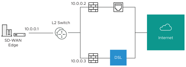
The following paragraph describes how the final configuration is defined.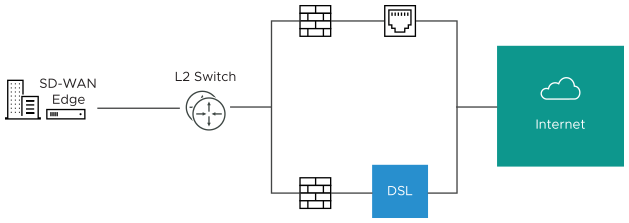
- The interface is defined with IP address 10.0.0.1 and next hop 10.0.0.2. Because more than one WAN link is attached to the interface, the links are set to “user defined.”
- The Cable link is defined and inherits the IP address of 10.0.0.1 and next hop of 10.0.0.2. No changes are required. When a packet needs to be sent out the cable link, it is sourced from 10.0.0.1 and forwarded to the device that responds to ARP for 10.0.0.2 (FW1). Return packets are destined for 10.0.0.1 and identified as having arrived on the cable link.
- The DSL link is defined, and because it is the second WAN link, the SD-WAN Orchestrator flags the IP address and next hop as mandatory configuration items. The user specifies a custom virtual IP (e.g. 10.0.0.4) for the source IP and 10.0.0.3 for the next hop. When a packet needs to be sent out the DSL link, it is sourced from 10.0.0.4 and forwarded to the device that responds to the ARP for 10.0.0.3 (FW2). Return packets are destined for 10.0.0.4 and identified as having arrived on the DSL link.
- Case 2: Two WAN links connected to an L3 switch/router: Alternatively, the upstream device may be an L3 switch or a router. In this case, the next hop device is the same (the switch) for both WAN links, rather than different (the firewalls) in the previous example. Often this is leveraged when the firewall sits on the LAN side of the SD-WAN Edge.
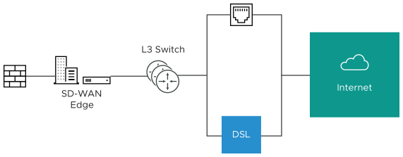
In this topology, policy-based routing will be used to steer packets to the appropriate WAN link. This steering may be performed by the IP address or by the VLAN tag, so we support both options.
Steering by IP: If the L3 device is capable of policy-based routing by source IP address, then both devices may reside on the same VLAN. In this case, the only configuration required is a custom source IP to differentiate the devices.
The following paragraph describes how the final configuration is defined.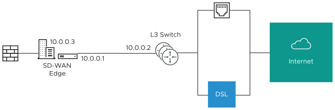
- The interface is defined with IP address 10.0.0.1 and next hop 10.0.0.2. Because more than one WAN link is attached to the interface, the links are set to “user defined.”
- The Cable link is defined and inherits the IP address of 10.0.0.1 and next hop of 10.0.0.2. No changes are required. When a packet needs to be sent out the cable link, it is sourced from 10.0.0.1 and forwarded to the device that responds to ARP for 10.0.0.2 (L3 Switch). Return packets are destined for 10.0.0.1 and identified as having arrived on the cable link.
- The DSL link is defined, and because it is the second WAN link, the SD-WAN Orchestrator flags the IP address and next hop as mandatory configuration items. The user specifies a custom virtual IP (for example, 10.0.0.3) for the source IP and the same 10.0.0.2 for the next hop. When a packet needs to be sent out the DSL link, it is sourced from 10.0.0.3 and forwarded to the device that responds to the ARP for 10.0.0.2 (L3 Switch). Return packets are destined for 10.0.0.3 and identified as having arrived on the DSL link.
Steering by VLAN: If the L3 device is not capable of source routing, or if for some other reason the user chooses to assign separate VLANs to the cable and DSL links, this must be configured.
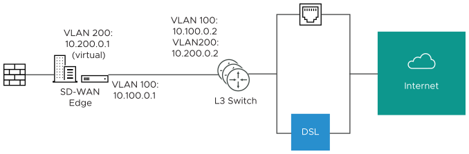
- The interface is defined with IP address 10.100.0.1 and next hop 10.100.0.2 on VLAN 100. Because more than one WAN link is attached to the interface, the links are set to “user defined.”
- The Cable link is defined and inherits VLAN 100 as well as the IP address of 10.100.0.1 and next hop of 10.100.0.2. No changes are required. When a packet needs to be sent out the cable link, it is sourced from 10.100.0.1, tagged with VLAN 100 and forwarded to the device that responds to ARP for 10.100.0.2 on VLAN 100 (L3 Switch). Return packets are destined for 10.100.0.1/VLAN 100 and identified as having arrived on the cable link.
- The DSL link is defined, and because it is the second WAN link the SD-WAN Orchestrator flags the IP address and next hop as mandatory configuration items. The user specifies a custom VLAN ID (200) as well as virtual IP (e.g. 10.200.0.1) for the source IP and the 10.200.0.2 for the next hop. When a packet needs to be sent out the DSL link, it is sourced from 10.200.0.1, tagged with VLAN 200 and forwarded to the device that responds to the ARP for 10.200.0.2 on VLAN 200 (L3 Switch). Return packets are destined for 10.200.0.1/VLAN 200 and identified as having arrived on the DSL link.
- Case 3: One-arm Deployments: One-arm deployments end up being very similar to other L3 deployments.
Again, the SD-WAN Edge shares the same next hop for both WAN links. Policy-based routing can be done to ensure that traffic is forwarded to the appropriate destination as defined above. Alternately, the source IP and VLAN for the WAN link objects in the VMware may be the same as the VLAN of the cable and DSL links to make the routing automatic.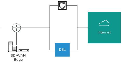
- Case 4: One WAN link reachable over multiple interfaces: Consider the traditional gold site topology where the MPLS is reachable via two alternate paths. In this case, we must define a custom source IP address and next hop that can be shared regardless of which interface is being used to communicate.
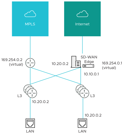
- GE1 is defined with IP address 10.10.0.1 and next hop 10.10.0.2
- GE2 is defined with IP address 10.20.0.1 and next hop 10.20.0.2
- The MPLS is defined and set as reachable via either interface. This makes the source IP and next hop IP address mandatory with no defaults.
- The source IP and destination are defined, which can be used for communication irrespective of the interface being used. When a packet needs to be sent out the MPLS link, it is sourced from 169.254.0.1, tagged with the configured VLAN and forwarded to the device that responds to ARP for 169.254.0.2 on the configured VLAN (CE Router). Return packets are destined for 169.254.0.1 and identified as having arrived on the MPLS link.
Note: If OSPF or BGP is not activated, you may need to configure a transit VLAN that is the same on both switches to allow reachability of this virtual IP.
