


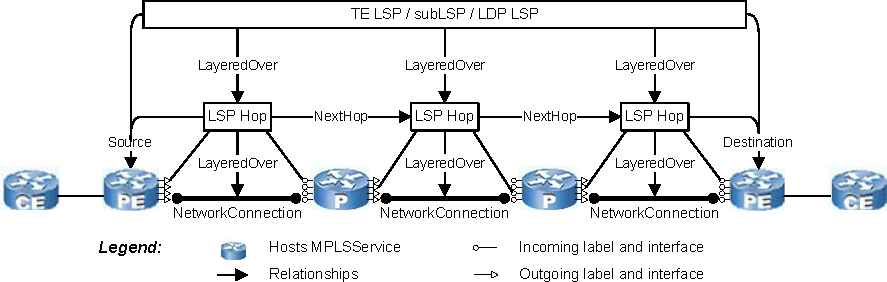
During the MPLS discovery process, the MPLS Topology Servercreates within its repository a data model representation of the discovered MPLS topology. The MPLS data model is shown in LSP modeling in MPLS data modelthrough RSVP session modeling in MPLS data model.


Typically, every relationship has an inverse relationship. For example, the relationship “Underlying” is the inverse relationship of “LayeredOver.”
GUID-7ACB6B1A-FD33-40C0-B5F3-7903A2882FD5.html#GUID-7ACB6B1A-FD33-40C0-B5F3-7903A2882FD5___MPLS_DISCO_PROCESS_38631and GUID-7ACB6B1A-FD33-40C0-B5F3-7903A2882FD5.html#GUID-7ACB6B1A-FD33-40C0-B5F3-7903A2882FD5___MPLS_DISCO_PROCESS_93469present descriptions of the MPLSService, LSP, LSPHop, LdpProtocolEndpoint, LdpAdjacency, RsvpProtocolEndpoint, and RsvpSession classes. More detailed descriptions of these classes are available in the VMware Smart Assurance MPLS Management Suite User Guide.
A TE tunnel and the TE LSPs that are associated with the TE tunnel originate on a PE or P device and terminate on a PE or P device. A P2MP LSP originates on a PE device and terminates on multiple PE devices; the subLSPs that are associated with the P2MP LSP originate on a PE device and terminate on a PE device. An LDP LSP originates on a PE device and terminates on a PE device.
