


The Optical Transport Manager for WDM uses object classes that represent each type of element to populate the VMware Smart Assurance repository that models the topology of the WDM network being managed. This, in turn, is used to build the codebook, which is the basis for root-cause analysis. The Optical Transport Manager for WDM also uses the relationships in the topology to calculate the impact that a root-cause problem in one element has on the elements and services that are connected to, or depend on it.
The model for WDM is more granular than that for SONET/SDH because there are fiber connections inside devices that are potential failure points and must therefore be part of the model.
As an example of what needs to be modeled in a WDM device, Schematic of a terminal end amplifier is a schematic of a WDM Transmit End Terminal device. This illustrates how the various components are connected together to take a number of incoming SONET/SDH services, convert them each to a WDM signal on a wavelength, and then combine the wavelengths onto a single fiber.
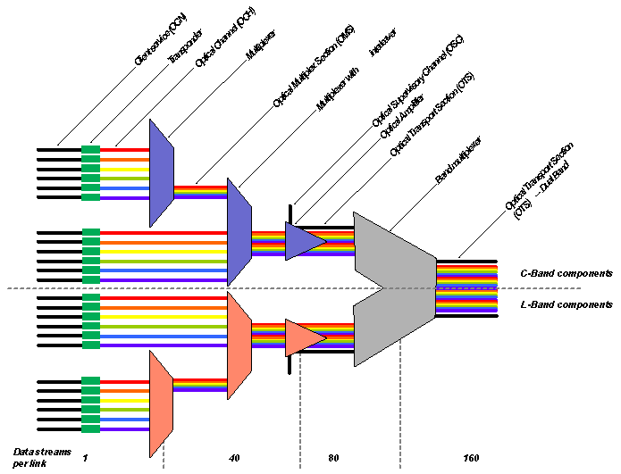
Each incoming client signal is converted to an Optical Channel (OCH), which carries the signal on a specific wavelength and adds a WDM header. A number of wavelengths are combined into a single fiber using a Multiplexer. Due to physical limitations, several stages of multiplexing are required to, for instance, combine 160 wavelengths onto a single fiber. In the example shown, 80 wavelengths in the C-band are combined in two stages of multiplexing, and are then combined with 80 other wavelengths in the L-band. The Optical Supervisory Channel (OSC), which carries management information on an additional wavelength, is added in the optical amplifier that is in each band’s path in front of the Band Multiplexer.
A WDM Receive End Terminal performs the reverse function in a similar arrangement. Other functions, such as in-line amplifiers and back-to-back amplifiers are made up of combinations of similar components.
