


Here are instructions for installing VMware Tanzu Application Service for VMs (TAS for VMs) on vSphere with NSX-T internal networking, using the VMware NSX-T Container plug-in for Ops Manager.
These instructions use the NSX-T Policy API, the next-generation interface for integrating with the NSX-T networking and security framework.
TAS for VMs uses a Container Network Interface (CNI) plug-in to support secure and direct internal communication between containers.
-
The internal Silk plugin that comes packaged with TAS for VMs, or
-
On vSphere, the NSX-T Container Plug-in (NCP), which is installed as the VMware NSX-T Container Plug-in for Ops Manager tile in Ops Manager.
Prerequisites
Before deploying TAS for VMs with NSX-T networking, you must have the following:
-
An NSX-T environment with NSX-T components installed and configured. The NSX-T version must support the versions of NCP and TAS for VMs you intend to use. Verify the compatibility between NSX-T, NCP and TAS for VMs with the following documentation:
- Product Interoperability Matrix: TAS for VMs, VMware NSX-T, and VMware NSX-T Container Plug-in for Ops Manager for supported version combinations.
- VMware NSX-T Data Center Documentation. In particular, review the NSX Container Plug-in (NCP) Release Notes and NSX-T Data Center Installation Guide for the versions of NCP and NSX-T that you want to install.
-
BOSH and Ops Manager installed and configured on vSphere. For more information, see Deploying Ops Manager on vSphere and Configuring BOSH Director on vSphere.
-
The VMware NSX-T Container Plug-in for Ops Manager tile is downloaded from VMware Tanzu Network and imported to the Ops Manager Installation Dashboard. For information about downloading and importing VMware Tanzu products to the Installation Dashboard, see Add and Import Products in Adding and Deleting Products.
-
The TAS for VMs tile is downloaded from VMware Tanzu Network and imported to the Ops Manager Installation Dashboard. The TAS for VMs tile must be in one of these states:
- Configured but not currently deployed. You did not click Review Pending Changes, then Apply Changes on this version of TAS for VMs.
- Deployed previously, with the Container network interface plugin field set to External in the Networking pane of the TAS for VMs tile.
class=“note important”> Important Deploying TAS for VMs with its container network interface (CNI) set to Silk configures Diego Cells to use an internally-managed container network. Subsequently switching the CNI interface to External NSX-T leads to errors.
Architecture
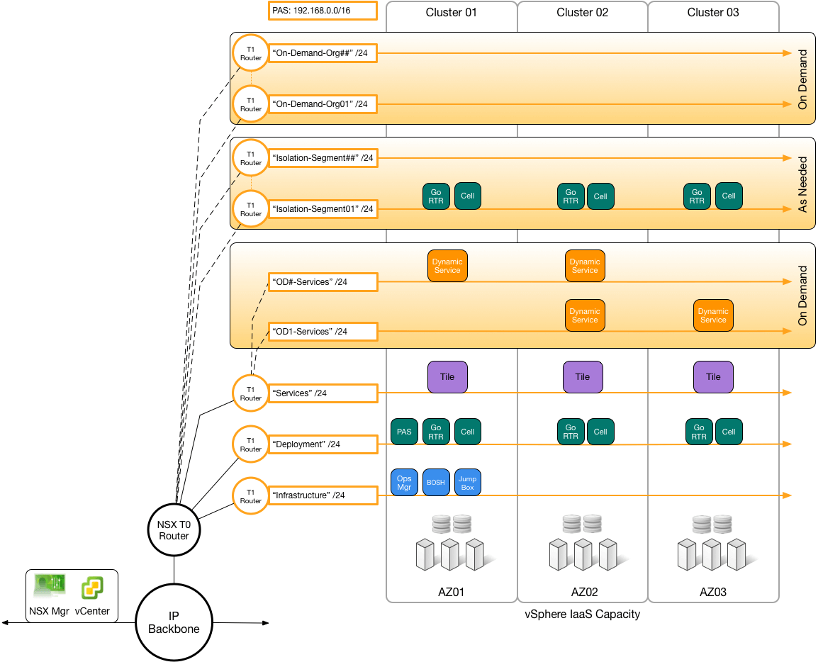
The following graphic shows how to deploy an NSX-T machine to run TAS for VMs across multiple vSphere hardware clusters. NSX-T runs a Tier-0 (T0) gateway and multiple Tier-1 (T1) gateways, each connecting to a network within Ops Manager. Each vSphere hardware column cluster corresponds to an Availability Zone (AZ) in Ops Manager: The NXT T0 Router is connected between the IP Backbone and the T1 Routers. The T1 Routers each terminate on a network. Three network types are shown: On-demand Orgs, Isolation Segments, and On-demand Services.
Install and Configure TAS for VMs and NSX-T
Installing NSX-T to run with TAS for VMs requires:
Set Up NSX-T to Integrate with TAS for VMs
To set up NSX-T to integrate with TAS for VMs, complete these procedures:
Configure Logical Switches
To configure logical switches:
-
In vSphere, create logical network switches to correspond to the networks that Ops Manager uses.
- Log in to the NSX-T Manager Dashboard.
- Go to Advanced Networking & Security.
- Go to the Switching pane.
-
For each of these networks:
- Infrastructure (BOSH and Ops Manager, defined in the Assign AZs and Networks pane of the BOSH Director tile)
- Deployment (TAS for VMs, defined in the Assign AZs and Networks pane of the TAS for VMs tile)
- Services and Dynamic Services (marketplace services and on-demand services, also defined in the TAS for VMs tile)
-
Isolation Segment (optional, defined in the Assign AZs and Networks pane of the Isolation Segment tile) do the following:
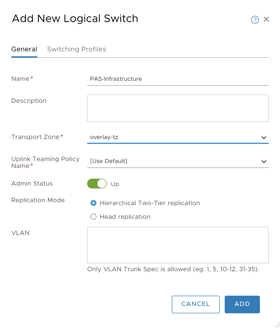
- Click +ADD.
- Enter a name for the logical switch (such as
TAS for VMs-Infrastructure,TAS for VMs-Deployment). -
Click ADD.
Configure Routers
Configure NAT Rules
-
Create T0 network address translation (NAT) rules to communicate with Ops Manager:
-
Create network address translation (NAT) rules to communicate with Ops Manager:
- Go to Networking.
- Go to the NAT pane.
- Select your T0 gateway.
- Click ADD NAT RULE.
- Add a rule for destination NAT (DNAT) with:
-
Create T1 routers for TAS for VMs, to connect from the T0 router. For each Ops Manager network, Infrastructure, Deployment, and so on, create a T1 router as follows:
-
In the NSX-T Manager UI, navigate to Advanced Networking & Security > Routing > Routers.
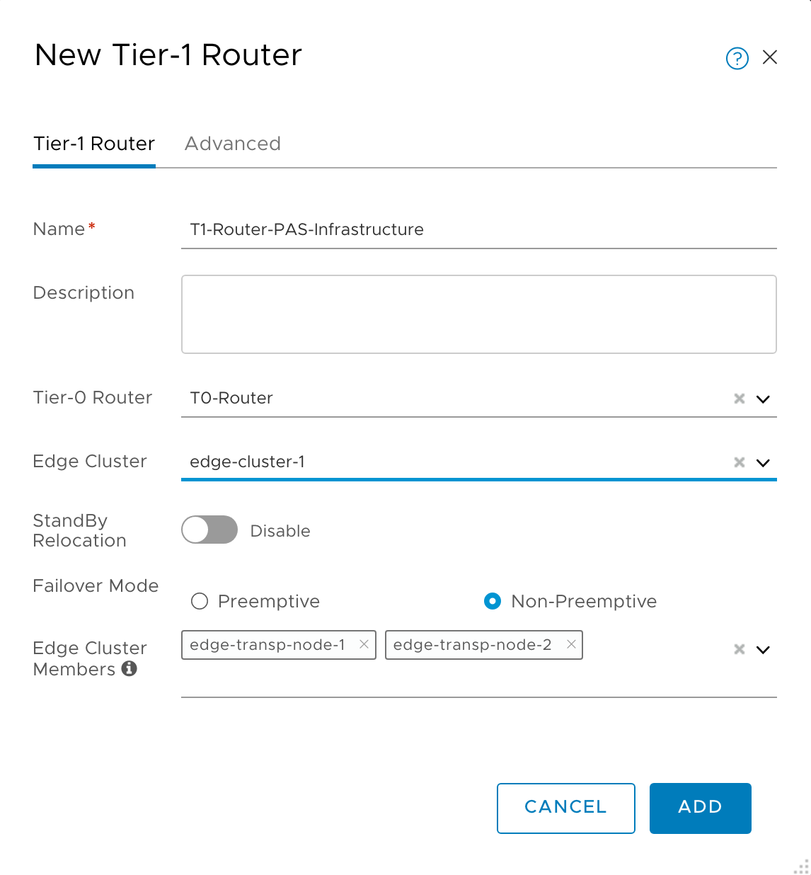
- Click +ADD > Tier-1 Router.
-
Configure the router. Include the Edge Cluster and Edge Cluster Members; they are required to enable the Load Balancer. The Infrastructure network router configuration might look like the following diagram:
-
Create T1 router downlink ports for TAS for VMs. For each T1 router you created, add a New Router Port as follows, to allow traffic in and out:
- In the NSX-T Manager UI, select the T1 router.
- In Configuration > Router Ports, click +ADD to add a new router port.
- For Logical Switch, enter the name of the logical switch you defined for the network in Add New Logical Switch, above.
-
For IP Address, use the first IP of the appropriate subnet. In this example, 192.168.1.0/24 is set aside for Infrastructure (Ops Manager and BOSH Director), and 192.168.2.0/24 for the Deployment, so 192.168.1.1 and 192.168.2.1 are used respectively.

-
Advertise the routes of the T1 routers to the T0 router, so the T0 router can correctly route incoming requests based on their destination IP address:
-
Create T1 gateways for TAS for VMs, to connect from the T0 gateway. For each Ops Manager network, Infrastructure, Deployment, and so on, create a T1 gateway as follows:
- In the NSX-T Manager UI, go to Networking, then Tier-1 Gateways.
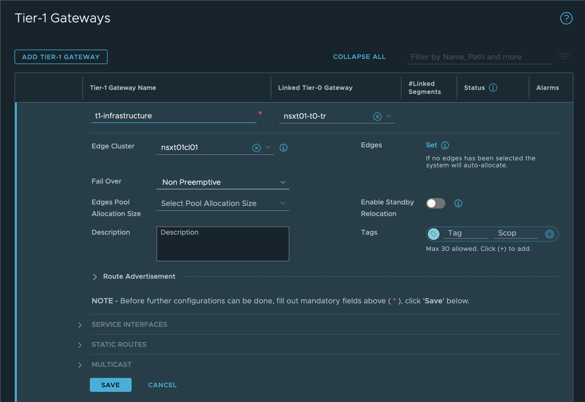
- Click ADD TIER-1 GATEWAY.
- Configure the gateway. Include the Edge Cluster, as it is required to enable the Load Balancer. The Infrastructure network gateway configuration looks similar to the following image:
-
Advertise the routes of the T1 gateways to the T0 gateway, so the T0 gateway can correctly route incoming requests based on their destination IP addresses:
- Edit your T1 Gateway and go to Route Advertisement.
- Activate All Connected Segments & Service Ports.
- Activate All LB VIP Routes. (necessary if Load Balancing service is configured).
-
Allocate an IP block for TAS for VMs orgs.
- From the NSX-T Manager, go to Networking, then IP Address Pools, click "IP ADDRESS BLOCKS tab, and click ADD IP ADDRESS BLOCK.
- Enter a name (for example,
TAS for VMs-container-ip-block). This IP block name is also used in the VMware NSX-T tile in the NCP section under IP Blocks of Container Networks. - Enter a description, such as
Subnets are allocated from this pool to each newly-created org. - Enter a CIDR to allocate an address block large enough to accommodate all TAS for VMs apps. A
/14CIDR is large enough for ~1,000 Orgs with ~250 apps each. If you are planning such a large foundation, see VMware NSX-T TAS for VMs limits in the VMware documentation.
-
Allocate an IP block for TAS for VMs orgs.
- From the NSX-T Manager, go to Networking, then IP Address Pools, click the IP Address Blocks tab, and click Add IP Address Block.
- Enter a name (for example,
TAS for VMs-container-ip-block). This IP block name is also used in the VMware NSX-T tile in the NCP section under IP Blocks of Container Networks. - Enter a description, such as
Subnets are allocated from this pool to each newly-created org. - Enter a CIDR to allocate an address block large enough to accommodate all TAS for VMs apps. A
/14CIDR is large enough for approximately 1,000 Orgs with about 250 apps each. If you are planning a large foundation, see VMware NSX-T TAS for VMs limits in the VMware documentation.
Configure Segments
-
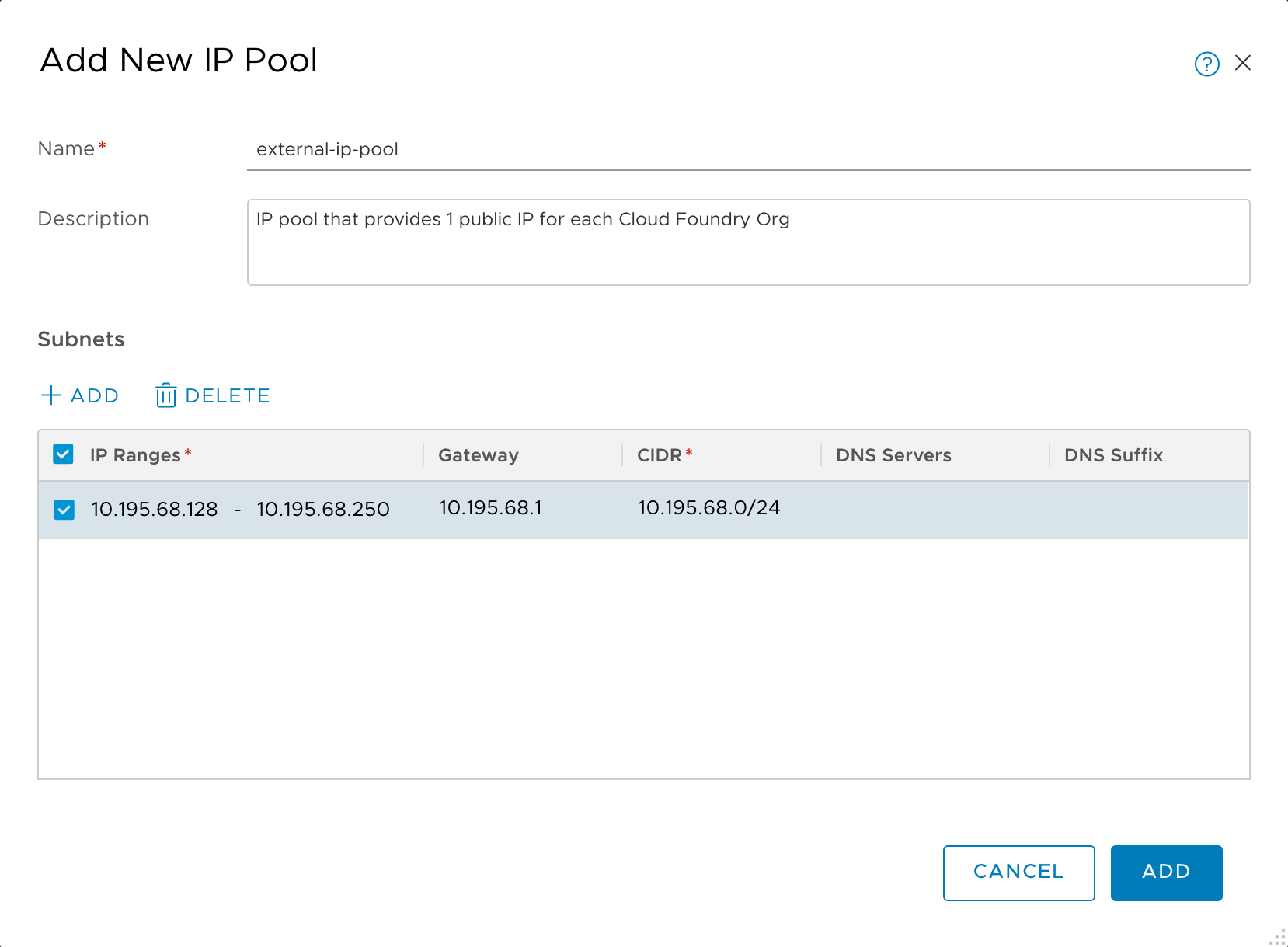
Create an external SNAT IP pool:
- Go to Networking, then IP Address Pools.
- Click the IP Address Pools tab and then click Add IP Address Pool.
- Enter a name (for example,
external-ip-pool). - Enter a description (for example, “IP pool that provides 1 public IP for each TAS for VMs Org”). Later, you enter this pool name, on the VMware NSX-T tile, in the NCP section, under IP Pools used to provide External (NAT) IP Addresses to Org Networks.
-
Set a subnet of externally-routable IP addresses for future NAT IP addresses.
-
In vSphere, create segments that correspond to the networks that Ops Manager uses.
- Log in to the NSX-T Manager Dashboard.
- Go to Networking.
- Go to the Segments pane.
- For each of these networks…
- Infrastructure (BOSH and Ops Manager, defined in the Assign AZs and Networks pane of the BOSH Director tile)
- Deployment (TAS for VMs, defined in the Assign AZs and Networks pane of the TAS for VMs tile)
- Services and Dynamic Services (marketplace services and on-demand services, also defined in the TAS for VMs tile)
- Isolation Segment (optional, defined in the Assign AZs and Networks pane of the Isolation Segment tile) …do the following:
- Click ADD SEGMENT.
- Enter a name for the segment.
- Enter a Gateway to connect to.
- Click SAVE.
-
In vSphere, create segments that correspond to the networks that Ops Manager uses.
- Log in to the NSX-T Manager Dashboard.
- Go to Networking.
- Go to the Segments pane.
- For each of these networks…
- Infrastructure (BOSH and Ops Manager, defined in the Assign AZs and Networks pane of the BOSH Director tile)
- Deployment (TAS for VMs, defined in the Assign AZs and Networks pane of the TAS for VMs tile)
- Services and Dynamic Services (marketplace services and on-demand services, also defined in the TAS for VMs tile)
- Isolation Segment (optional, defined in the Assign AZs and Networks pane of the Isolation Segment tile) …do the following:
- Click ADD SEGMENT.
- Enter a name for the segment
- Enter a Gateway to connect to.
- Click SAVE.
Configure Load Balancer
- Create Active Monitors (health checks) for use by the virtual servers later.
- In the NSX-T Manager UI, go to Networking, then Load Balancing, and click the Monitors tab.
- Create the health monitor for web load balancing:
- Click Add Active Monitor.
- Select HTTP.
- Name:
tas-web-monitor - Monitoring Port: 8080
- Monitoring Port: 8080
- Name:
- Configure Additional Properties:
- HTTP Request URL:
/health - HTTP Response Code: 200
- HTTP Request URL:
- Click Save.
- Create the health monitor for TCP load balancing:
- Click ADD ACTIVE MONITOR.
- Select HTTP.
- Name:
tas-tcp-monitor - Monitoring Port: 80
- Name:
- Configure Additional Properties:
- HTTP Request URL:
/health - HTTP Response Code: 200
- HTTP Request URL:
- Click Save.
-
Create the health monitor for SSH load balancing:
- Click ADD ACTIVE MONITOR.
- Select TCP:
- Name:
tas-ssh-monitor - Monitoring Port: 2222
- Name:
- Click Save.
-
Create Server Pools (collections of VMs that handle traffic) for use by the virtual servers.
- In the NSX-T Manager UI, go to Networking, then Load Balancing, and click the Server Pools tab.
- Create the server pool for web load balancing:
- Click Add Server Pool to add a new pool.
- Name:
tas-web-pool
- Name:
- Enter SNAT Translation:
Automap - Click Select Members:
- Membership Type:
Static
- Membership Type:
- Click Active Monitor Set:
- Select
tas-web-monitor - Click Apply
- Select
- Click Save.
-
Create the server pool for TCP load balancing:
- Click Add Server Pool to add a new pool.
- Name:
tas-tcp-pool
- Name:
- Enter SNAT Translation:
Disabled - Click Select Members:
- Membership Type:
Static
- Membership Type:
- Click Active Monitor Set:
- Select
tas-tcp-monitor - Click Apply
- Select
- Click Save.
- Click Add Server Pool to add a new pool.
-
Create the server pool for SSH load balancing:
- Click ADD SERVER POOL to add a new pool.
- Name:
tas-ssh-pool
- Name:
- Enter SNAT Translation:
Disabled - Click Select Members:
- Membership Type:
Static
- Membership Type:
- Click Active Monitor Set:
- Select
tas-ssh-monitor - Click Apply
- Select
- Click Save.
- Click ADD SERVER POOL to add a new pool.
-
Create the load balancer. In the NSX-T Manager UI, go to Networking, then Load Balancing, and click the Load Balancers tab.
- Click Add Load Balancer.
- Enter the fields:
- Name:
tas-lb - Load Balancer Size: Select
Smallunless you have a larger Foundation. - Attachment:
t1-deploymentAttach your load balancer to the Tier 1 gateway fronting your deployment instances.
- Name:
- Click Save
- Click Yes when prompted Want to continue configuring this Load Balancer?
- Click Virtual Servers Set
- Enter the fields:
- Click Add Load Balancer.
-
Click Add Active Monitor.
- Select HTTP:
- Name:
tas-web-monitor - Monitoring Port: 8080.
- Name:
- Configure Additional Properties:
- HTTP Request URL:
/health - HTTP Response Code: 200.
- HTTP Request URL:
- Click Save.
To create the health monitor for TCP load balancing:
- Click Add Active Monitor.
- Select HTTP:
- Name:
tas-tcp-monitor - Monitoring Port: 80.
- Name:
- Configure Additional Properties:
- HTTP Request URL:
/health - HTTP Response Code: 200
- HTTP Request URL:
- Click Save.
To create the health monitor for SSH load balancing:
- Click Add Active Monitor.
- Select TCP:
- Name:
tas-ssh-monitor - Monitoring Port: 2222.
- Name:
- Click Save.
To create Server Pools (collections of VMs which handle traffic) for use by the virtual servers:
- In the NSX-T Manager UI, go to Networking, then Load Balancing.
- Click the Server Pools tab.
To create the server pool for web load balancing:
- Click Add Server Pool : Name:
tas-web-pool - Enter SNAT Translation:
Automap - Click Select Members: Membership Type:
Static - Click Active Monitor Set:
tas-web-monitor - Click Apply
- Click Save.
To create the server pool for TCP load balancing:
-
Click Add Server Pool to add a new pool.
- Name:
tas-tcp-pool- Enter SNAT Translation:
Disabled - Click Select Members: Membership Type:
Static - Click Active Monitor Set:
tas-tcp-monitor - Click Apply
- Click Save.
- Enter SNAT Translation:
- Name:
-
Create the server pool for SSH load balancing:
- Click Add Server Pool Name:
tas-ssh-pool - Enter SNAT Translation:
Disabled - Click Select Members: Membership Type:
Static - Click Active Monitor Set:
tas-ssh-monitor - Click Apply.
- Click Save.
- Click Add Server Pool Name:
To create the load balancer:
- In the NSX-T Manager UI, go to Networking, then Load Balancing.
- Click the Load Balancers tab.
- Click Add Load Balancer.
- Enter the fields:
- Name:
tas-lb - Load Balancer Size: Select
Smallunless you have a larger Foundation. - Attachment:
t1-deploymentAttach your load balancer to the Tier 1 gateway fronting your deployment instances.
- Name:
- Click Save.
- Click Yes, when prompted with, Want to continue configuring this Load Balancer?.
- Enter the fields:
To create the virtual server that forwards unencrypted web (HTTP) traffic to the foundation:
Important For foundations requiring end-to-end encryption, do not enable the virtual server on port 80. If it must be enabled, configure it to redirect traffic to the encrypted port (443).
- Click Virtual Servers Set.
- Click Add Virtual Server.
- Select L4 TCP.
- Name:
tas-web-vs - Application Profile:
default-tcp-lb-app-profile - IP Address: use the address of the DNS record of
*.system.YOUR-SYSTEM-DOMAIN.com - Port:
80,443 - Server Pool:
tas-web-pool
- Name:
- Click Save.
To create the virtual server that forwards traffic to apps with custom tcp ports to the foundation:
- Click Add Virtual Server.
- Select L4 TCP.
- Name:
tas-tcp-vs - Application Profile:
default-tcp-lb-app-profile - IP Address: Use the address of the DNS record of
tcp.apps.YOUR-SYSTEM-DOMAIN.com - Port: Use the same ports as configured in the TAS for VMs Tile, then Networking, and TCP Routing Ports. For example:
1024-1123,5900 - Server Pool:
tas-tcp-pool
- Name:
- Click Save.
To create the virtual server that forwards SSH traffic to the foundation:
- Click Add Virtual Server.
- Select L4 TCP.
- Name:
tas-ssh-vs - Application Profile:
default-tcp-lb-app-profile - IP Address: Use the address of the DNS record of
ssh.system.YOUR-SYSTEM-DOMAIN.com. - Port:
2222 - Server Pool:
tas-ssh-pool
- Name:
- Click Save.
Enable NSX-T Mode in the BOSH Director
To enable NSX-T mode in the BOSH Director:
-
From the Ops Manager Installation Dashboard, open the BOSH Director tile.
-
In the vCenter Configs pane, click the pencil icon for the vCenter Config you want to edit.
-
Select NSX Networking below.
-
Configure BOSH Director authentication to the NSX Manager by following the NSX Networking instructions in the Step 2: Configure vCenter section of Configuring BOSH Director on vSphere.
-
Verify that the Use NSX-T Policy API option is selected.
Configure TAS for VMs for External Container Networking
To configure TAS for VMs for external container networking:
-
If you have not already done so, download the TAS for VMs tile from VMware Tanzu Network and import it to the Installation Dashboard.
For instructions, see Add and Import Products.

-
Configure TAS for VMs, following the directions in Configuring TAS for VMs. When you configure Networking, select External under Container networking interface plugin.
Install and configure the NSX-T container plug-In
- Configure TAS for VMs to add router, diego_brain, and tcp_router instances to the corresponding NSX-T server pools upon deployment.
- Open the TAS for VMs tile, then click the Resource Config pane.
- Click the arrow next to each job to reveal the NSX-T Configuration column.
- Under Logical Load Balancer, complete the JSON
server_poolslist with the NSX-T Server Pool these instance must be added to upon deployment.- router -> tas-web-pool
- diego_brain -> tas-ssh-pool
- tcp_router -> tas-tcp-pool
- Click Save
Install and Configure the NSX-T Container Plug-In
To install and configure the tile:
-
If you have not already done so, download the VMware NSX-T Container Plug-in for Ops Manager tile from VMware Tanzu Network and import it to the Installation Dashboard. For instructions, see Add and Import Products.
1. If you are using VMware Workspace ONE Access, formerly called VMware Identity Manager (vIDM), then select **Client Certificate Authentication**. 1. Otherwise, select **Basic Authentication with Username and Password** and enter **NSX Manager Admin Username** and **Admin Password** credentials in the fields underneath.-
NSX Manager CA Cert: Obtain this certificate from NSX-T Manager as follows:
sshinto NSX-T Manager using the admin account that you created when you deployed NSX-T Manager.-
From the NSX-T Manager command line, run
get certificate apito retrieve the certificate.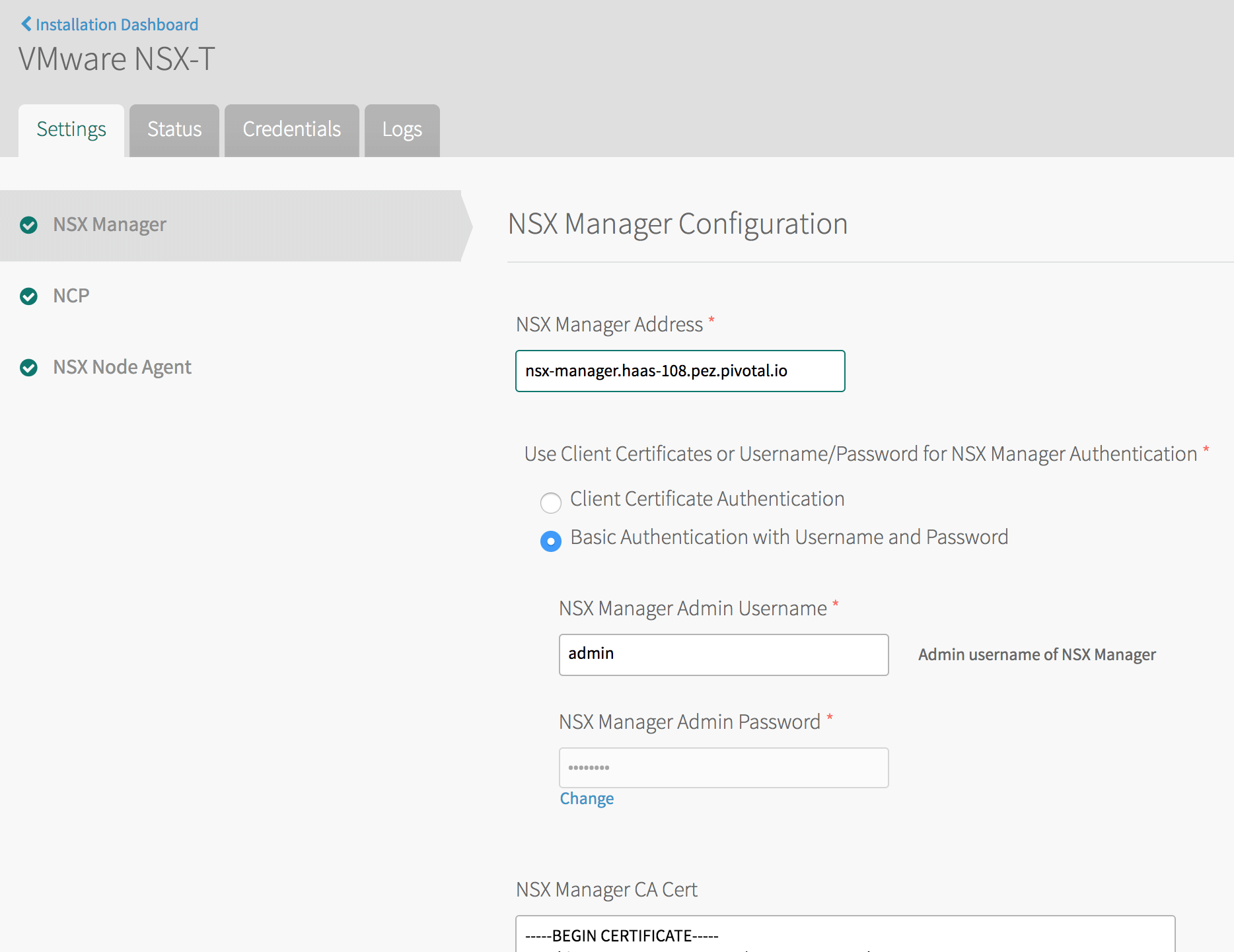
-
-
Open and configure the NCP (NSX-T Container Plugin) pane as follows:
- TAS for VMs Foundation Name: If unsure, use
TAS for VMs. If multiple foundations co-exist on the same NSX-T Manager, choose a unique string, such asTAS for VMs-beta. NCP creates artifacts, such as T1 gateways and prefixes their names with this string for easy identification. - Overlay Transport Zone: A uniquely identifying string for the Transport Zone that you chose when you created segments for each network. This can be the name of the transport zone if no other zones in NSX-T share the same name, or else the UUID for the transport zone.
- Tier-0 Router: A uniquely identifying string for the T0 gateway. This can be the tag string that you gave the gateway in NSX-T Manager if no other T0 gateways in NSX-T share the same name, or else the UUID for the gateway.
- IP Blocks of Container Networks: Use the same IP block created Configure Gateways.
- Subnet Prefix of Container Networks: Subnet mask to set the address range size for apps in a single org. Defaults to
24. This number must be higher than the mask for all TAS for VMs orgs in the NSX-T Manager New IP Block pane, to define each org’s fraction of the total TAS for VMs address space. - IP Pools used to provide External (NAT) IP Addresses to Org Networks: Use the same IP Pool created iin Configure Gateways.
- Enable NSX-T Policy API: Enable this check box to use the new Policy API.
- TAS for VMs Foundation Name: If unsure, use
-
In the NSX Node Agent pane, enable the Enable Debug Level of Logging for NSX Node Agent check box.

-
Click Save and return to the Installation Dashboard.
-
After you have configured both the TAS for VMs tile and the VMware NSX-T tile, click Review Pending Changes, then Apply Changes to deploy TAS for VMs with NSX-T networking.
Upgrade TAS for VMs with NSX-T networking
After you have deployed TAS for VMs with NSX-T, you may need to upgrade either Ops Manager, TAS for VMs, the NSX-T Container Plug-in or NSX-T Data Center. If you upgrade one of these components, you may need to upgrade the other components as well.
For example, if you want to upgrade NSX-T Data Center, you may need to upgrade the NSX-T Container Plug-in first.
To upgrade TAS for VMs with NSX-T Networking:
-
Plan the upgrade by determining the compatibility of NCP, NSX-T and TAS for VMs by checking the following documentation:
- See Product Interoperability Matrix: TAS for VMs, VMware NSX-T, and VMware NSX-T Container Plug-in for Ops Manager for supported version combinations.
- See VMware NSX-T Data Center Documentation. In particular, review the NSX Container Plug-in (NCP) Release Notes and NSX-T Data Center Installation Guide for the versions of NCP and NSX-T that you want to install.
-
Download the desired version of VMware NSX-T Container Plug-in for Ops Manager tile from VMware Tanzu Network.
-
In Ops Manager, import the new version of the tile to the Installation Dashboard. For instructions, see Adding and Importing Products.
-
Click Review Pending Changes and review your changes.
-
Click Apply Changes.
-
Continue with the upgrade of Ops Manager, TAS for VMs, or NSX-T Data Center. For more information, see Upgrade NCP in a Ops Manager Environment in the VMware NSX-T Data Center documentation.
