


This topic describes how to install and configure NSX Data Center v3.0 for use with VMware Tanzu Kubernetes Grid Integrated Edition (TKGI) on vSphere.
Prerequisites
Before completing this section, make sure you have completed the following sections:
- NSX-T Installation Prerequisites
- Install and Configure the NSX-T Manager Hosts
- Generate and Register the NSX-T TLS Certificate and Private Key
- Create an IP Pool for VTEP
- Configure Transport Zones
- Configure vSphere Networking for ESXi Hosts
- Deploy NSX-T Edge Nodes
Prerequisites for Installing NSX-T Data Center v3.0 for Tanzu Kubernetes Grid Integrated Edition
To perform a new installation of NSX-T Data Center for Tanzu Kubernetes Grid Integrated Edition, complete the following steps in the order presented.
Deploy ESXi Host Transport Nodes Using VDS
Deploy each ESXi host in the COMPUTE-cluster as an ESXi host transport node (TN) in NSX-T. If you have not created a separate COMPUTE-cluster for ESXi hosts, deploy each ESXi host in the vSphere cluster as a host transport node in NSX-T.
-
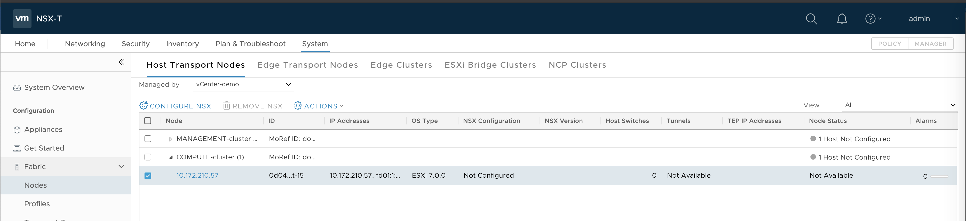
Go to System > Fabric > Nodes > Host Transport Nodes.
-
Expand the Compute Manager and select the ESXi host in the COMPUTE-cluster, or each ESXi host in the vSphere cluster.
-
Click Configure NSX.
-
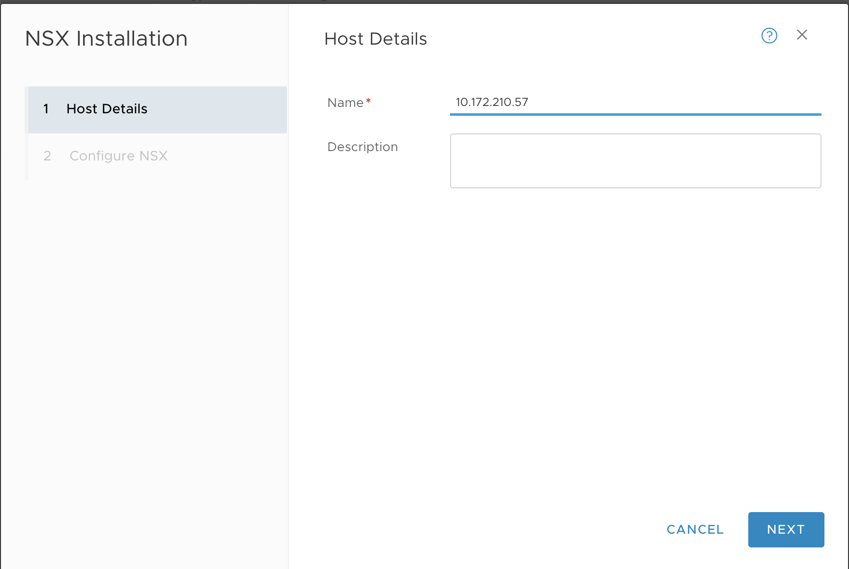
In the Host Details tab, enter a name, such as
10.172.210.57. -
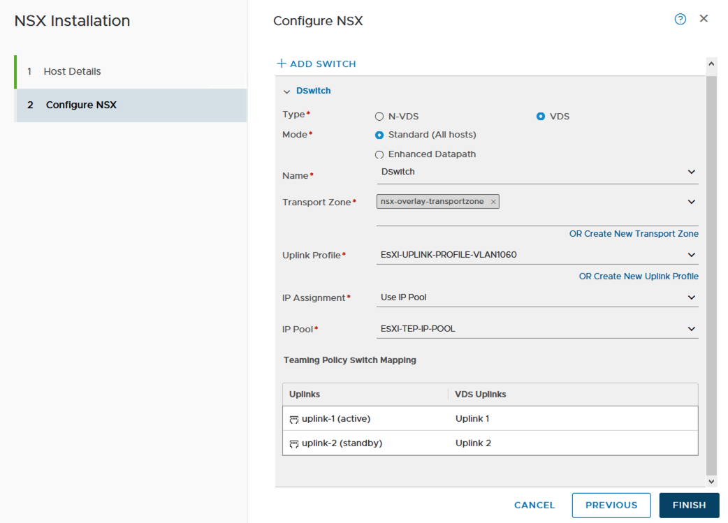
In the Configure NSX tab, configure the transport node as follows:
- Type:
VDS(do not select the N-VDS option) - Name:
switch-overlay(you must use the same switch name that was configured fortz-overlaytransport zone) - Transport Zone:
tz-overlay - NIOC Profile:
nsx-default-nioc-hostswitch-profile - Uplink Profile:
nsx-esxi-uplink-hostswitch-profile - LLDP Profile:
LLDP [Send Packet Disabled] - IP Assignment:
Use IP Pool - IP Pool:
TEP-IP-POOL - Teaming Policy Switch Mapping
- Uplinks:
uplink-1 - Physical NICs:
vmnic1
- Uplinks:
- Type:
-
Click Finish.
-
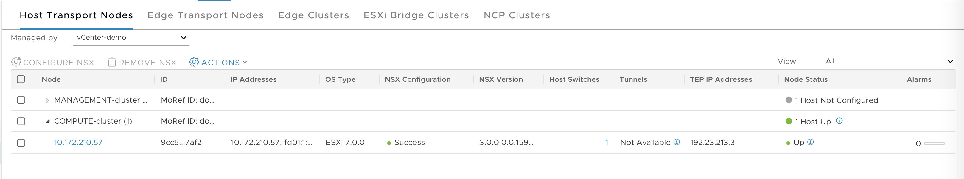
Verify that the host TN is configured.
Verify TEP to TEP Connectivity
To avoid any overlay communication in the future due to MTU issue, test TEP to TEP connectivity and verify that it is working.
-
SSH to edge-node-1 and get the local TEP IP address, such as
192.23.213.1. Use the commandget vtepsto get the IP. -
SSH to edge-node-2 and get the local TEP IP address, ushc as
192.23.213.2. Use the commandget vtepsto get the IP. -
SSH to the ESXi host and get the TEP IP address, such as
192.23.213.3. Use the commandesxcfg-vmknic -lto get the IP. The interface will bevmk10and the NetStack will bevxlan. -
From each ESXi transport node, test the connections to each NSX-T Edge Node, for example:
# vmkping ++netstack=vxlan 192.23.213.1 -d -s 1572 -I vmk10: OK # vmkping ++netstack=vxlan 192.23.213.2 -d -s 1572 -I vmk10: OK-
Test the connection from NSX-T edge node 1 and edge node 2 to ESXi TN:
> vrf 0 > ping 192.23.213.1 size 1572 dfbit enable: OK -
Test the connection from NSX-T edge node 1 to NSX-T edge node 2:
> vrf 0
> ping 192.23.213.2 size 1572 dfbit enable: OK
-
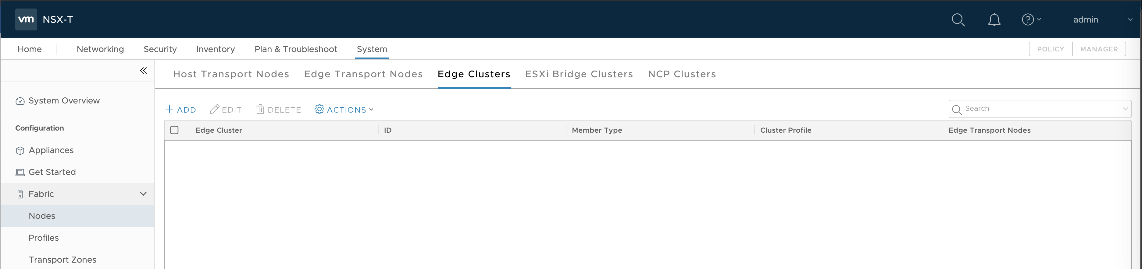
Create NSX-T Edge Cluster
-
Go to System > Fabric > Nodes > Edge Clusters.
-
Click Add.
- Enter a name, such as
edge-cluster-1. - Add members, including
edge-node-1andedge-node-2.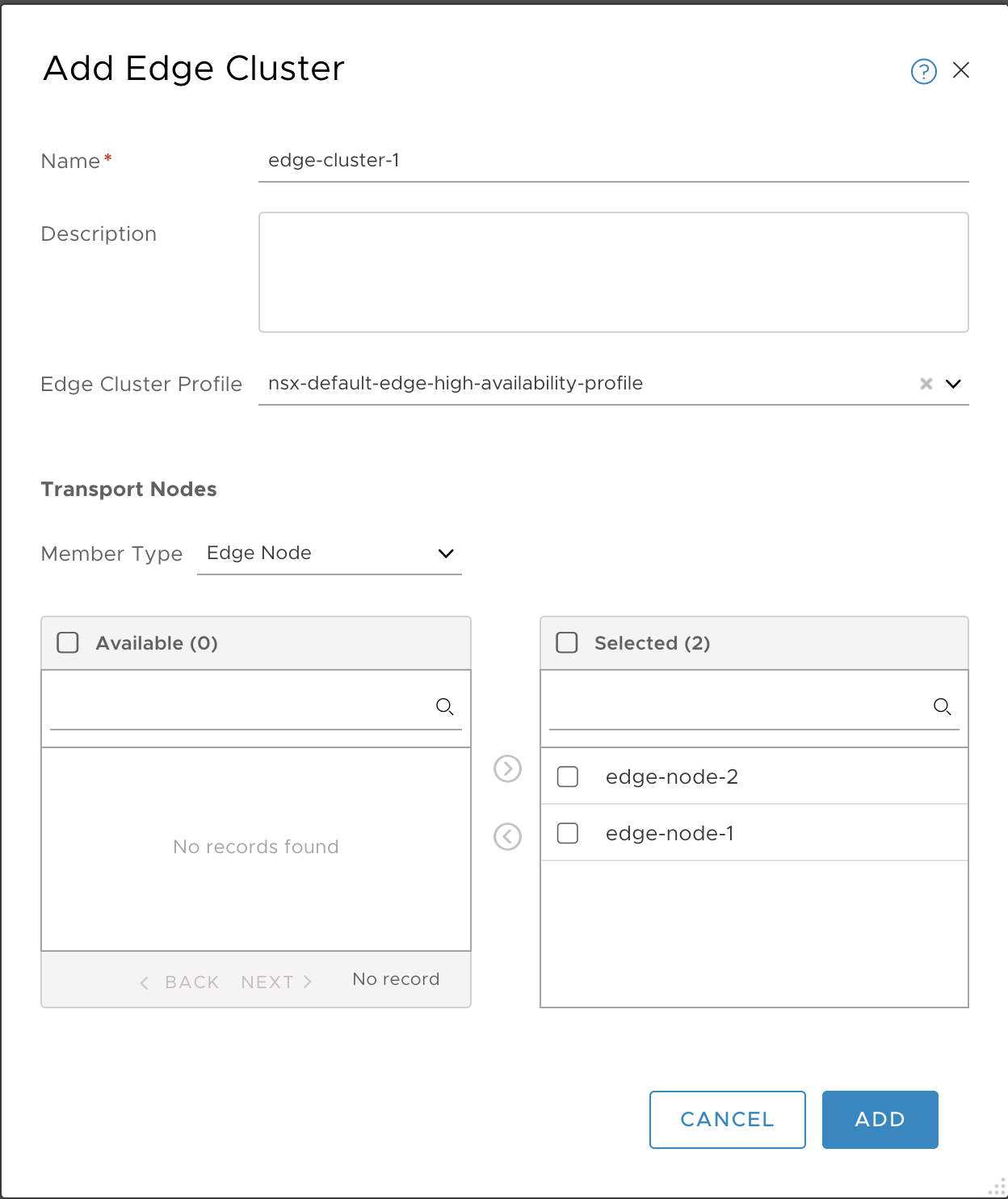
- Enter a name, such as
-
Click Add.
-
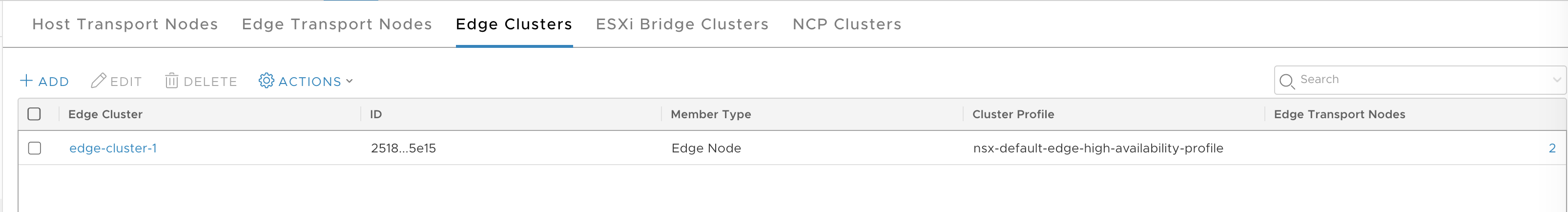
Verify.
Create Uplink Logical Switch
Create an uplink Logical Switch to be used for the Tier-0 Router.
-
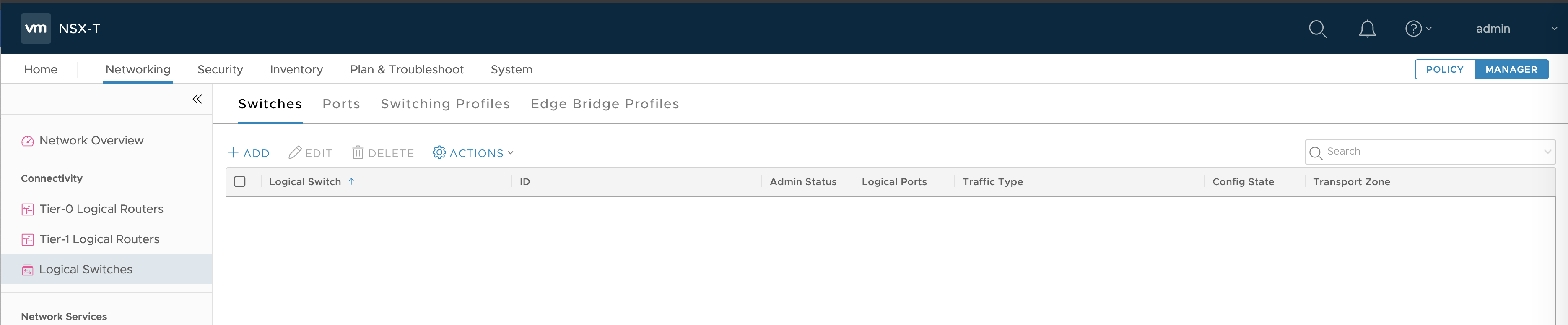
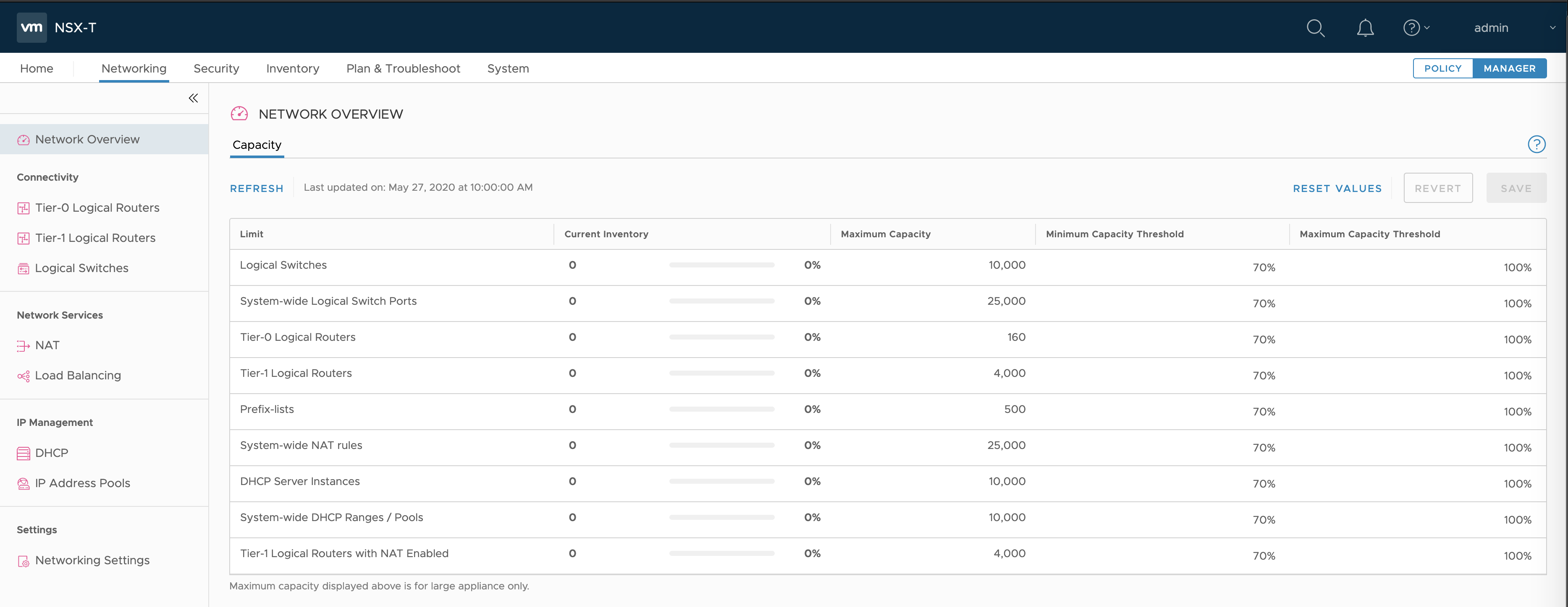
At upper-right, select the Manager tab.
-
Go to Networking > Logical Switches.
-
Click Add.
-
Configure the new logical switch as follows:
- Name:
LS-T0-uplink - Transport Zone:
tz-vlan - VLAN:
1548
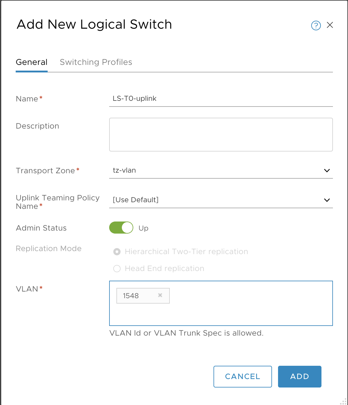
- Name:
-
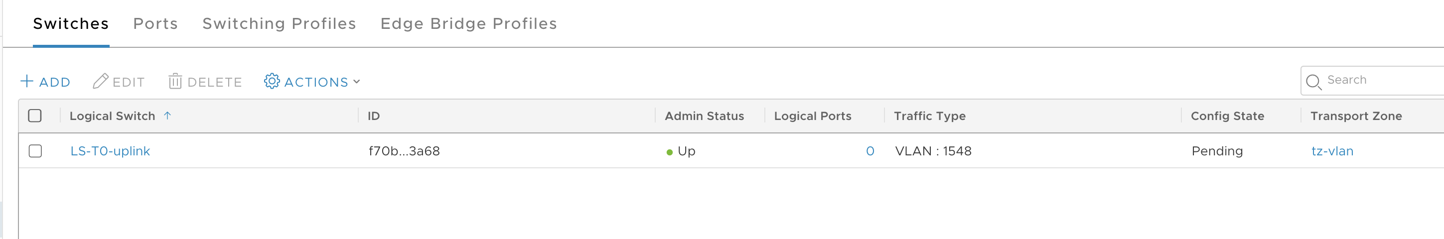
Click Add.
-
Verify.
Create Tier-0 Router
-
Select Networking from the Manager tab.
-
Select Tier-0 Logical Router.
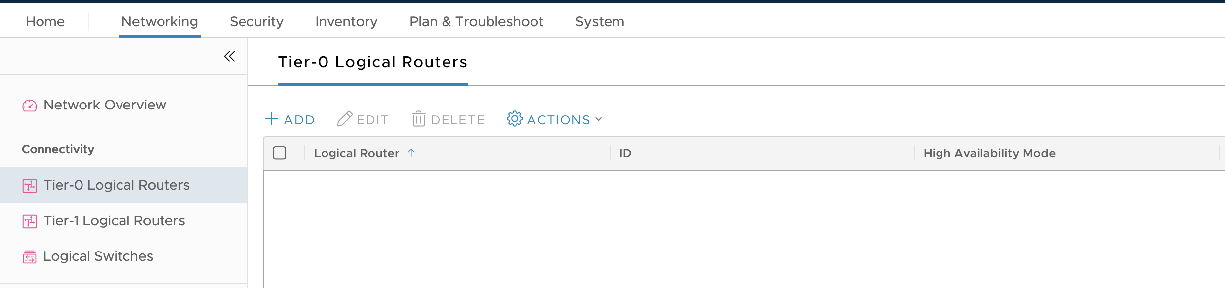
-
Click Add.
-
Configure the new Tier-0 Router as follows:
- Name:
T0-router - Edge Cluster:
edge-cluster-1 - HA mode: Either
Active-ActiveorActive-Standby - Failover mode:
Non-Preemptive
Note: Configuring Failover mode is optional if HA mode is configured as
Active-Active. For more information on NSX-T HA mode configuration, see Add a Tier-0 Gateway in the VMware NSX-T Data Center documentation.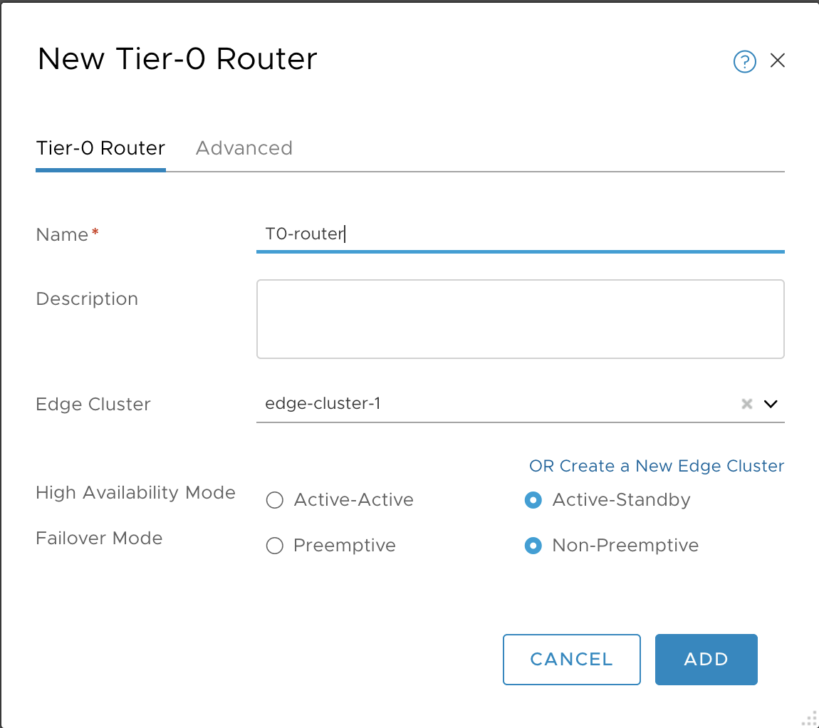
- Name:
-
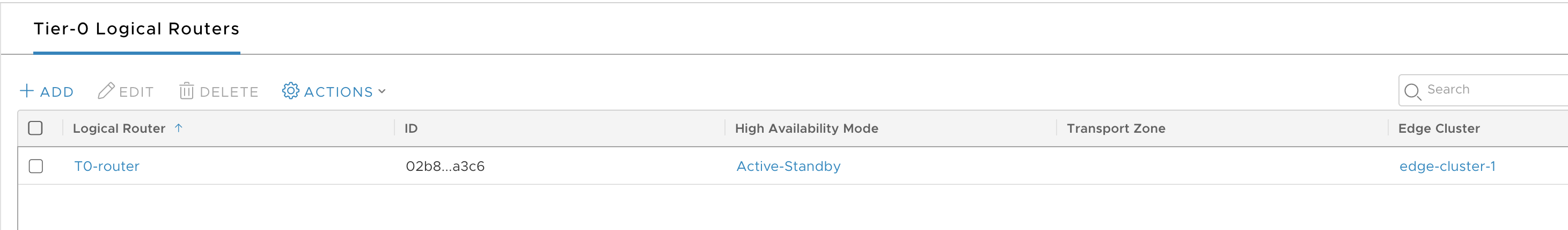
Click Save and verify.
-
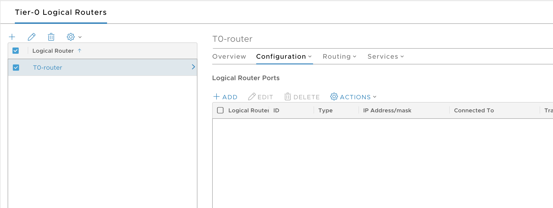
Select the T0 router.
-
Select Configuration > Router Ports.
-
Click Add.
-
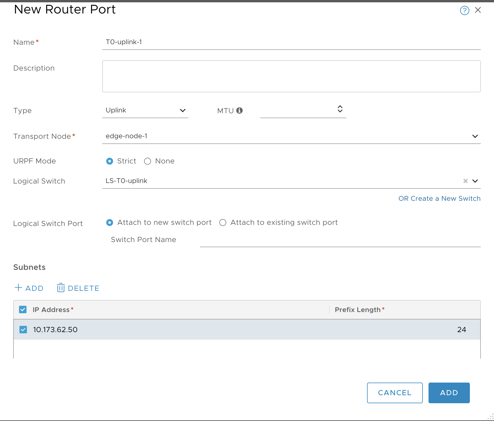
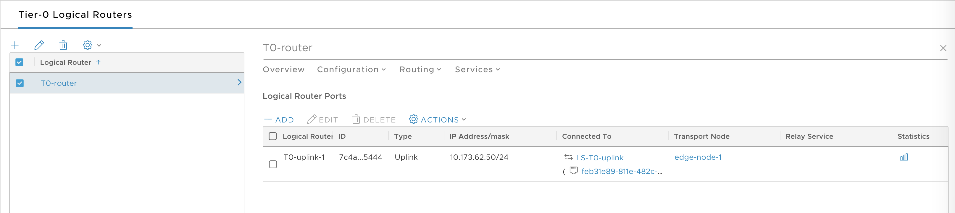
Configure a new router port as follows:
- Name: T0-uplink-1
- Type: uplink
- Transport Node: edge-node-1
- Logical Switch: LS-T0-uplink
- Logical Switch Port: Attach to a new switch port
- Subnet: 10.173.62.50 / 24
-
Click Add and verify.
-
Select the T0 router.
-
Select Configuration > Router Ports.
-
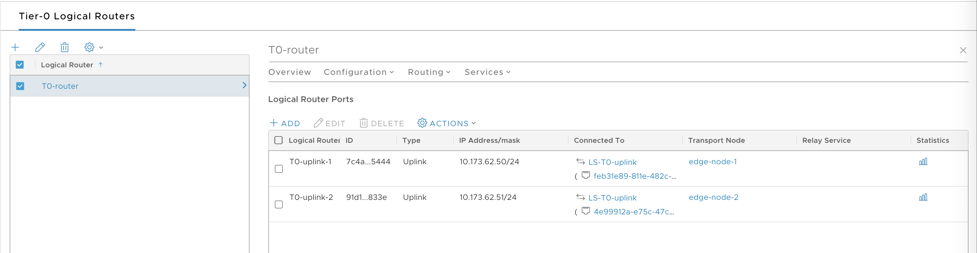
Add a second uplink by creating a second router port for edge-node-2:
- Name: T0-uplink-1
- Type: uplink
- Transport Node: edge-node-2
- Logical Switch: LS-T0-uplink
- Logical Switch Port: Attach to a new switch port
- Subnet: 10.173.62.51 / 24
-
Once completed, verify that you have two connected router ports.
Next Steps
Create NSX-T Objects for Kubernetes Clusters Provisioned by TKGI.
