In a vSphere IaaS control plane environment, a Supervisor can either use a vSphere networking stack or NSX to provide connectivity to Supervisor control plane VMs, services, and workloads.
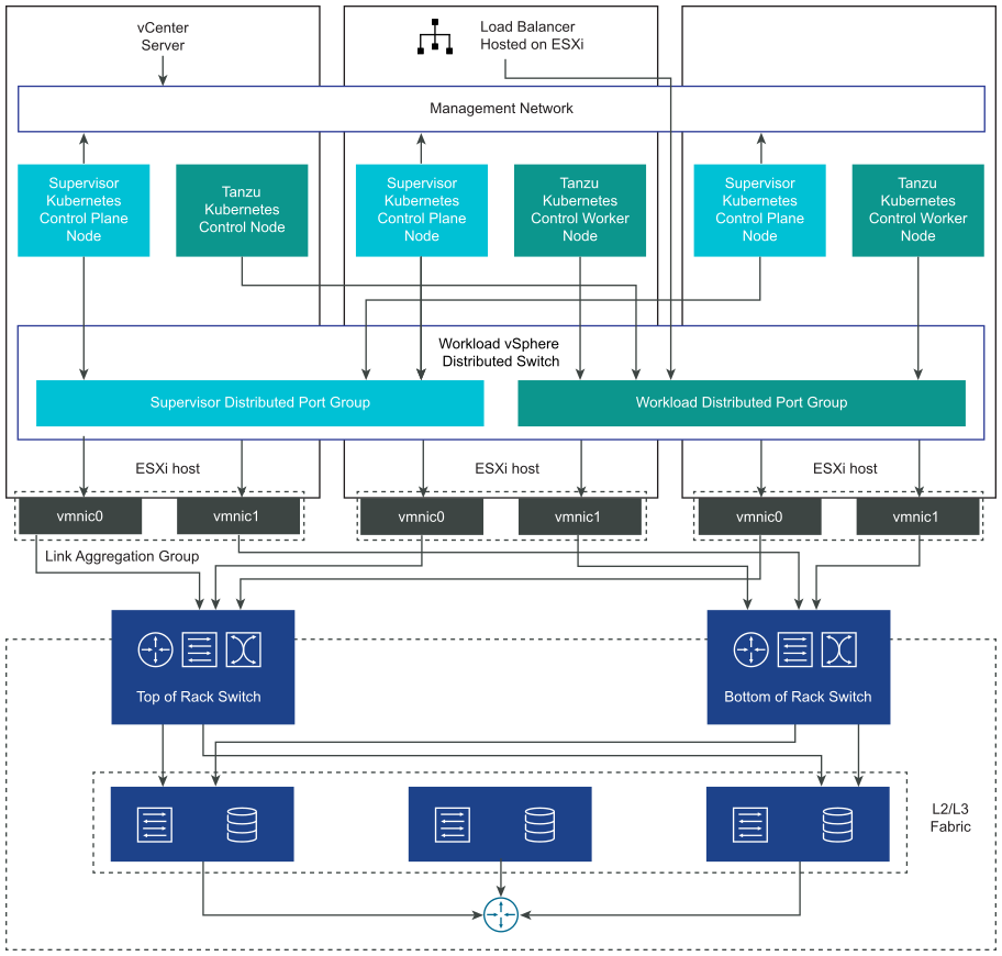
When a Supervisor is configured with the vSphere networking stack, all hosts from the Supervisor are connected to a vDS that provides connectivity to workloads and Supervisor control plane VMs. A Supervisor that uses the vSphere networking stack requires a load balancer on the vCenter Server management network to provide connectivity to DevOps users and external services.
- NSX version is 4.1.1 or later.
- The NSX Advanced Load Balancer version is 22.1.4 or later with the Enterprise license.
- The NSX Advanced Load Balancer Controller you plan to configure is registered on NSX.
- An NSX load balancer is not already configured on the Supervisor.
Supervisor Networking with VDS
In a Supervisor that is backed by VDS as the networking stack, all hosts from the vSphere clusters backing the Supervisor must be connected to the same VDS. The Supervisor uses distributed port groups as workload networks for Kubernetes workloads and control plane traffic. You assign workload networks to namespaces in the Supervisor.
Depending on the topology that you implement for the Supervisor, you can use one or more distributed port groups as workload networks. The network that provides connectivity to the Supervisor control plane VMs is called Primary workload network. You can assign this network to all the namespaces on the Supervisor, or you can use different networks for each namespace. The TKG clusters connect to the Workload Network that is assigned to the namespace where the clusters reside.
A Supervisor that is backed by a VDS uses a load balancer for providing connectivity to DevOps users and external services. You can use the NSX Advanced Load Balancer or the HAProxy load balancer.
For more information, see Install and Configuring NSX Advanced Load Balancer and Install and Configure HAProxy Load Balancer.
In a single-cluster Supervisor setup, the Supervisor is backed by only one vSphere cluster. All hosts from the cluster must be connected to a VDS.

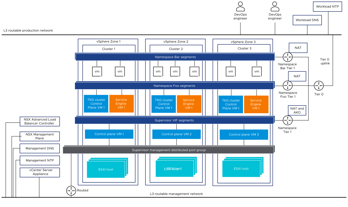
In a three-zone Supervisor, you deploy the Supervisor on three vSphere zones, each mapped to a vSphere cluster. All hosts from these vSphere clusters must be connected to the same VDS. All physical servers must be connected to a L2 device. Workload networks that you configure to namespace span across all three vSphere zones.

Supervisor Networking with NSX
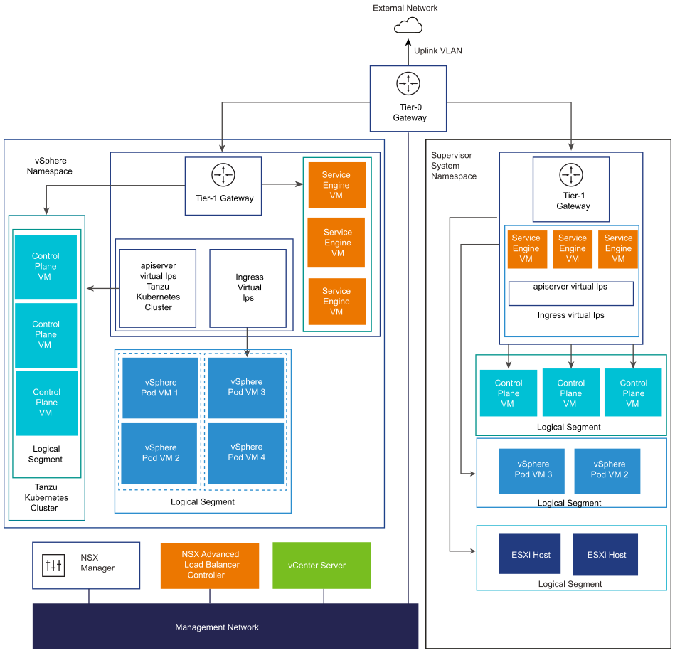
NSX provides network connectivity to the objects inside the Supervisor and external networks. Connectivity to the ESXi hosts comprising the cluster is handled by the standard vSphere networks.
You can also configure the Supervisor networking manually by using an existing NSX deployment or by deploying a new instance of NSX.
For more information, see Install and Configure NSX for vSphere IaaS control plane.

- NSX Container Plugin (NCP) provides integration between NSX and Kubernetes. The main component of NCP runs in a container and communicates with NSX Manager and with the Kubernetes control plane. NCP monitors changes to containers and other resources and manages networking resources such as logical ports, segments, routers, and security groups for the containers by calling the NSX API.
The NCP creates one shared tier-1 gateway for system namespaces and a tier-1 gateway and load balancer for each namespace, by default. The tier-1 gateway is connected to the tier-0 gateway and a default segment.
System namespaces are namespaces that are used by the core components that are integral to functioning of theSupervisor and TKG clusters. The shared network resources that include the tier-1 gateway, load balancer, and SNAT IP are grouped in a system namespace.
- NSX Edge provides connectivity from external networks to Supervisor objects. The NSX Edge cluster has a load balancer that provides a redundancy to the Kubernetes API servers residing on the Supervisor control plane VMs and any application that must be published and be accessible from outside the Supervisor.
- A tier-0 gateway is associated with the NSX Edge cluster to provide routing to the external network. The uplink interface uses either the dynamic routing protocol, BGP, or static routing.
- Each vSphere Namespace has a separate network and set of networking resources shared by applications inside the namespace such as, tier-1 gateway, load balancer service, and SNAT IP address.
- Workloads running in vSphere Pods, regular VMs, or TKG clusters, that are in the same namespace, share a same SNAT IP for North-South connectivity.
- Workloads running in vSphere Pods or TKG clusters will have the same isolation rule that is implemented by the default firewall.
- A separate SNAT IP is not required for each Kubernetes namespace. East west connectivity between namespaces will be no SNAT.
- The segments for each namespace reside on the VDS functioning in Standard mode that is associated with the NSX Edge cluster. The segment provides an overlay network to the Supervisor.
- Supervisors have separate segments within the shared tier-1 gateway. For each TKG cluster, segments are defined within the tier-1 gateway of the namespace.
- The Spherelet processes on each ESXi hosts communicate with vCenter Server through an interface on the Management Network.
In a three-zone Supervisor configured with NSX as the networking stack, all hosts from all three vSphere clusters mapped to the zones must use be connected to the same VDS and participate in the same NSX Overlay Transport Zone. All hosts must be connected to the same L2 physical device.

Supervisor networking with NSX and NSX Advanced Load Balancer
NSX provides network connectivity to the objects inside the Supervisor and external networks. A Supervisor that is configured with NSX can use the NSX Edge or the NSX Advanced Load Balancer.
The components of the NSX Advanced Load Balancer include the NSX Advanced Load Balancer Controller cluster, Service Engines (data plane) VMs and the Avi Kubernetes Operator (AKO).
The NSX Advanced Load Balancer Controller interacts with the vCenter Server to automate the load balancing for the TKG clusters. It is responsible for provisioning service engines, coordinating resources across service engines, and aggregating service engine metrics and logging. The Controller provides a Web interface, command-line interface, and API for user operation and programmatic integration.After you deploy and configure the Controller VM, you can deploy a Controller Cluster to set up the control plane cluster for HA.
The Service Engine, is the data plane virtual machine. A Service Engine runs one or more virtual services. A Service Engine is managed by the NSX Advanced Load Balancer Controller. The Controller provisions Service Engines to host virtual services.
- The first network interface,
vnic0of the VM, connects to the Management Network where it can connect to the NSX Advanced Load Balancer Controller. - The remaining interfaces,
vnic1 - 8, connect to the Data Network where virtual services run.
The Service Engine interfaces automatically connect to correct vDS port groups. Each Service Engine can support up to 1000 virtual services.
A virtual service provides layer 4 and layer 7 load balancing services for TKG cluster workloads. A virtual service is configured with one virtual IP and multiple ports. When a virtual service is deployed, the Controller automatically selects an ESX server, spins up a Service Engine, and connects it to the correct networks (port groups).
The first Service Engine is created only after the first virtual service is configured. Any subsequent virtual services that are configured use the existing Service Engine.
Each virtual server exposes a layer 4 load balancer with a distinct IP address of type load balancer for a TKG cluster. The IP address assigned to each virtual server is selected from the IP address block given to the Controller when you configure it.
The Avi Kubernetes operator (AKO) watches Kubernetes resources and communicates with the NSX Advanced Load Balancer Controller to request the corresponding load balancing resources. The Avi Kubernetes Operator is installed on the Supervisors as part of the enablement process.
For more information, see Install and Configure NSX and NSX Advanced Load Balancer.


- You cannot deploy the NSX Advanced Load Balancer Controller in an vCenter Server Enhanced Linked Mode deployment. You can only deploy the NSX Advanced Load Balancer Controller in a single vCenter Server deployment. If more than one vCenter Server is linked, only one of them can be used while configuring the NSX Advanced Load Balancer Controller.
- You cannot configure the NSX Advanced Load Balancer Controller in a multi-tier tier-0 topology. If the NSX environment is set up with a multi-tier tier-0 topology, you can only use one tier-0 gateway while configuring the NSX Advanced Load Balancer Controller.
Networking Configuration Methods with NSX
- The simplest way to configure the Supervisor networking is by using the VMware Cloud Foundation SDDC Manager. For more information, see the VMware Cloud Foundation SDDC Manager documentation. For information, see VMware Cloud Foundation Administration Guide.
- You can also configure the Supervisor networking manually by using an existing NSX deployment or by deploying a new instance of NSX. See Install and Configure NSX for vSphere IaaS control plane for more information.