


The path topology draws a detailed connection that exists between any two virtual machines in your environment.
The topology involves both Layer 3 and Layer 2 components. You can view this topology using the search query vm_name_1 to vm_name_2. If a path exists, the VM-to-VM path visualization proceeds to populate all the components that exist between vm_name_1 to vm_name_2 and also draws an animated path. If the routers are physical, then they are shown outside the boundary.
In the path topology, you see the VM-to-VM path between the source and the destination. If the default path is not configured between the VMs, an error message appears to inform that the path is not defined or the router interface is not found.
- Kubernetes Service to Kubernetes Service
- Kubernetes Service to Kubernetes Pod
- Kubernetes Pod to Kubernete Pod
Note: The path involving physical devices is not supported.
- Virtual Server name
- Load Balancer IP address
- Port number
- Load Balancer Algorithm
- The default gateway that was taken from the load balancer.
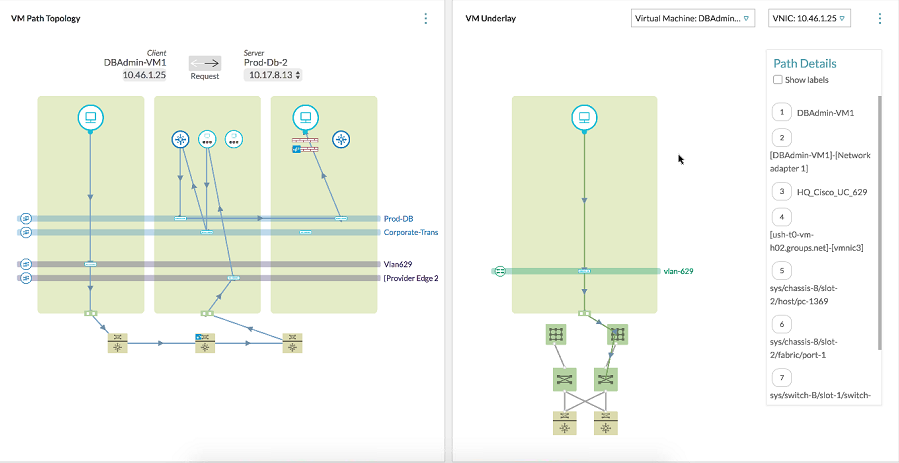
If you hover your mouse on any of the routers, edges, or LDRs that are involved in the path, the complete routing or NAT information is shown.
The VM Underlay section that is on the right side of the VM Path topology shows the underlay information of the VMs involved and their connectivity to the top of the rack switches and the ports involved. For Kubernetes entities, VM Underlay displays the VM or the Kubernetes node information on which the Pod resides.
In the VM underlay section, the components are labeled if you select Show labels under Path Details. In this section, the drop-down list at the top shows the endpoint VMs and the active VMs at the edges. For each edge VM, the neighboring drop-down menu shows the ingress and the egress interface IP addresses. Based on the selection, the underlay path for that particular interface is shown.
You can also reverse the path direction using the arrows on top of the topology map.
The topology map gives more visibility regarding the ports involved in the VM-VM path. In the Path Details section, the name of the actual port channel is shown.
