


This topic tells you about how multi-site replication works in VMware SQL with MySQL for Tanzu Application Service and contains information to help you decide whether to use multi-site replication.
Overview of Multi-Site Replication
Multi-site replication in VMware Tanzu for MySQL is a disaster recovery solution that lets developers provision two instances across two foundations, and then configure cross-foundation replication from the “leader” instance to the “follower” instance. Operators can configure the two foundations to be in the same data center or spread across multiple data centers or geographical regions.
The foundation types are:
-
Primary Foundation: This foundation is deployed in your main data center. Generally, this data center receives the majority of app traffic. VMware Tanzu for MySQL assumes that the leader is deployed on this foundation when it is healthy.
-
Secondary Foundation: This foundation is deployed in your failover data center. Generally, this data center receives less app traffic than the primary foundation, or no traffic at all. VMware Tanzu for MySQL assumes that the follower is deployed on this foundation unless a developer triggers a failover.
For information about enabling multi-site replication, see Preparing for multi-site replication.
For information for developers about using multi-site replication, see Using VMware Tanzu for MySQL for multi-site replication.
Multi-Site Replication Plans
In your secondary foundation, you always use a multi‑site replication for the replication follower instance.
In your primary foundation, you have a choice of service plan types for your replication leader instance: - multi‑site replication: this provisions a single node instance that can support multi-site replication. The resulting configuration resembles a leader-follower service instance, but with the two single-node instances deployed and replicating across two separate foundations. 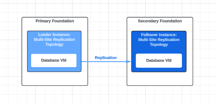
-
High-Availability Cluster (MySQL 8.0 only): this provisions a HA cluster of three database VM nodes in your leader foundation.
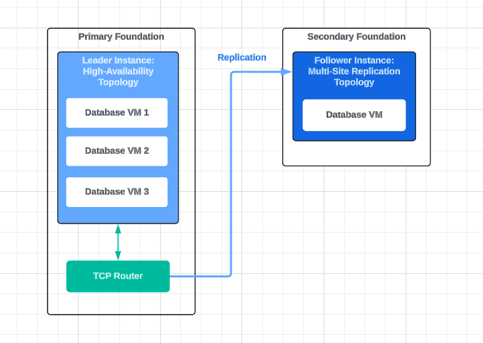
A HA cluster offers greater resilience to in-foundation outages. More information about HA clusters can be found in About highly available clusters.
Important VMware Tanzu for MySQL supports using a High-availability cluster service instance as a multi-site leader only for clusters running MySQL version 8.0.x or greater. The MySQL version is set in the plan definition section of Ops Manager; also see Configuring Service Plans.
To support multi-site replication from an HA cluster leader, the Operator must introduce TCP Routing by enabling Service-Gateway access for VMware Tanzu for MySQL. More information about Service-Gateway access can be found in About Service-Gateway access and and Enabling Service-Gateway access.
Note Service instances of type "Leader Follower" are not used for multi-site replication. This page uses the terms "leader" and "follower" to describe configuration of the two supported service instance types "Multi-Site Replication", and "HA cluster". For more information about Leader Follower service instances, see About Leader-Follower topology.
Multi-site replication benefits
Multi-site replication has the following benefits:
-
Resilience for Service Instances: Developers can trigger a failover to maintain app uptime during a data center outage. For more information, see Triggering multi-site replication failover and switchover.
-
Data Center Upgrades with Zero Downtime: Operators can upgrade data centers without taking databases offline by triggering a switchover first.
-
Support for Multiple Cloud Deployment Models: Operators can configure multi-site replication with a single cloud or hybrid cloud deployment model. Both deployment models have the same end-user experience.
-
Support for Active-Passive and App-Layer Active-Active Disaster Recovery: For more information, see About Active-Passive topology and About App-Layer Active-Active topology.
Active-Passive topology
In an active-passive topology, when all foundations and workloads are healthy, all app traffic is directed to the primary foundation. The secondary foundation receives no app traffic.
VMware recommends using this topology when your secondary foundation is scaled down, generally inactive, and does not receive significant app traffic.
For information about active-passive failover and switchover, see About failover and switchover.
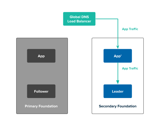
The following diagram describes the active-passive topology in a healthy state:
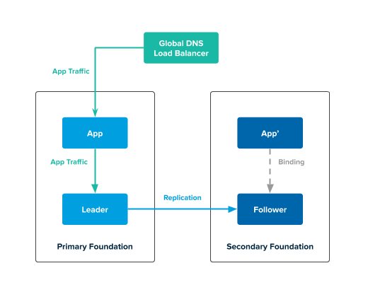
In the previous diagram:
- The global DNS load balancer (GLB) directs traffic to the app in the primary foundation. This app issues transactions to the leader service instance.
- The follower service instance in the secondary foundation continuously replicates data from the leader service instance in the primary foundation.
App-Layer Active-Active topology
In an app-layer active-active topology, when all foundations and workloads are healthy, app traffic is directed to both the primary and secondary foundation.
VMware recommends using this topology when both your primary and secondary foundations are scaled up and are expected to serve traffic.
For information about app-layer active-active failover and switchover, see About failover and switchover.
The following diagram describes the app-layer active-active topology in a healthy state:
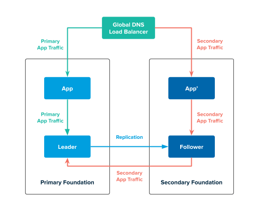
In the previous diagram:
-
The GLB directs traffic to the apps in the primary and secondary foundations. The apps in the primary and secondary foundation issue transactions to the leader service instance.
The app in the secondary foundation issues transactions to the leader:- Connects to the follower service instance
- Issues transactions to the follower service instance
- Forwards the transactions from the follower service instance to the leader
-
The follower service instance in the secondary foundation continuously replicates data from the leader service instance in the primary foundation.
In the Multi‑Site Replication plan, the app-layer active-active topology does not enable multi-primary replication. Therefore, the follower service instance is read-only. Apps can only write to the leader.
Important The app-layer active-active topology does not enable multi-primary (bidirectional) replication. The follower service instance is read-only, and apps can write only to the leader.Failover and switchover
VMware Tanzu for MySQL prioritizes data consistency over availability. Therefore, VMware Tanzu for MySQL does not trigger failover or switchover automatically and developers must manually trigger a failover or switchover. For instructions about triggering failover or switchover, see Triggering multi-site replication failover and switchover.
The following table describes when you can trigger a failover or switchover:
| Failover if... | Switchover if... |
|---|---|
|
|
For information about multi-site replication topologies in an healthy state, see About Active-Passive topology and About App-Layer Active-Active topology.
Failover
In both the active-passive and app-layer active-active topologies, if a developer triggers a failover, all app traffic is directed to the leader in the secondary foundation and the primary foundation receives no app traffic.
The following diagram describes what happens when you trigger a failover for a multi-site replication topology:
In the previous diagram:
- The GLB directs traffic to the app in the secondary foundation. This app issues transactions to the leader service instance in the secondary foundation.
- The leader service instance in the secondary foundation does not replicate data to another service instance.
Active-Passive switchover
In an active-passive topology, if a developer triggers a switchover, all app traffic is directed to the leader in the secondary foundation. The primary foundation receives no app traffic.
The following diagram describes what happens when you trigger a switchover in an active-passive topology:
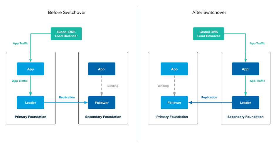
In the preceding diagram:
- The GLB directs traffic to the app in the secondary foundation. This app issues transactions to the leader service instance in the secondary foundation.
- The leader service instance in the secondary foundation replicates data to the follower service instance in the primary foundation.
App-Layer Active-Active switchover
If a developer triggers a switchover, app traffic is still directed to both the primary and secondary foundation. However, the leader service instance is in secondary foundation.
The following diagram describes what happens when you trigger a switchover in an active-active topology:
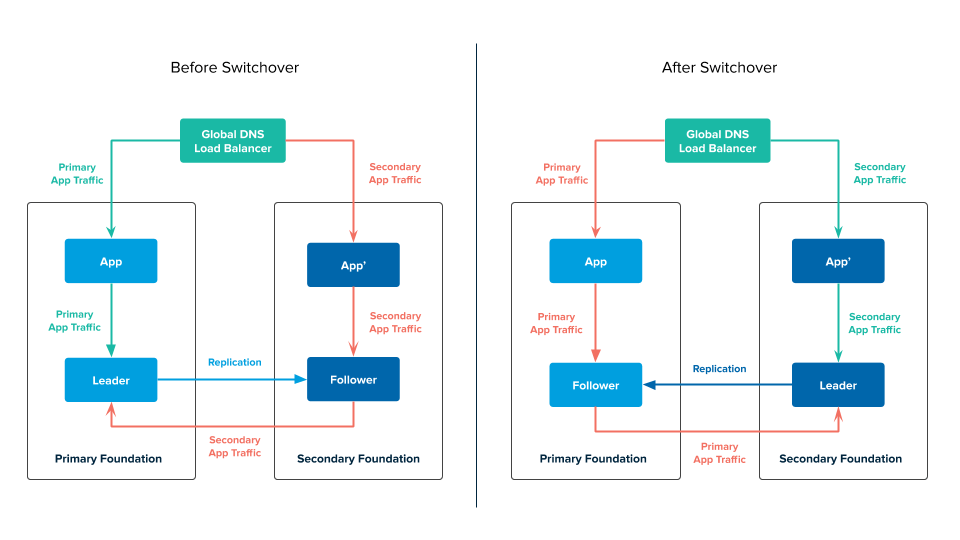
In the preceding diagram:
-
The GLB directs traffic to the apps in the primary and secondary foundations. The apps in the primary and secondary foundation issue transactions to the leader service instance in the secondary foundation.
The app in the primary foundation issues transactions to the leader:- Connects to the follower service instance.
- Issues transactions to the follower service instance.
- Forwards the transactions from the follower service instance to the leader.
-
The follower service instance in the primary foundation continuously replicates data from the leader service instance in the secondary foundation
About enabling external access
If external-access is enabled, replication can occur between two non-routable foundations. Replication traffic goes through tcp-router.
The following diagram describes what happens when you enable external-access for multi-site replication:
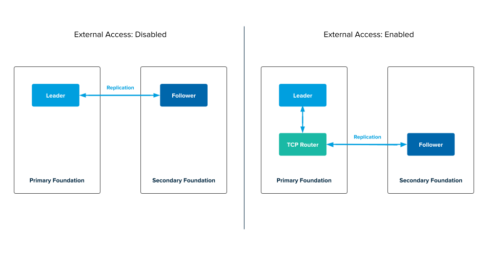
In the preceding diagram:
-
Before external-access is enabled, replication traffic goes directly to the follower.
-
After external-access is enabled, replication traffic goes through tcp-router to the follower.
Infrastructure requirements for multi-site configuration
Before you deploy a multi-site configuration, consider the following requirements.
Capacity planning
When calculating IaaS usage, take into account that each multi-site configuration deploys two service instances: a primary either of type multi‑site replication or HA cluster, and a secondary of type multi‑site replication. - Each multi‑site replication service instance deploys one VM. Therefore the smallest multi-site configuration deploys two VMs (one per foundation), twice the footprint of a service instance created from a single-node plan. - Each HA cluster service instance deploys four VMs. Therefore the largest multi-site configuration deploys five VMs, 5x the footprint of a service instance created from a single-node plan. - The above configurations initially deploy a single VM within your secondary foundation. During failover and switchover operations (which promote your secondary instance into a primary instance), you may elect to scale up your multi‑site replication secondary into a HA cluster primary. And a switchover from a HA cluster primary will downscale that instance to a multi‑site replication secondary. These scaling operations impact the distribution of VMs across your two foundations.
For more information, see Setting limits for on-demand service instances and Persistent Disk Usage.
Networking requirements
You must consider the multi‑site replication instances that are deployed in data centers are a geographically farther apart experience higher latencies.
For information about the standard networking rules, see Required Networking Rules for multi‑site replication.
Availability zones
With the addition of a new feature that allows scaling up and down between single node multisite leaders and Highly Available (HA) leaders, extra care must be taken to ensure that the availability zones (AZ) are compatible between the two plans.
To minimize impact of an availability zone (AZ) outage and to remove single points of failure, VMware recommends that you provision three AZs if using HA deployments. With three AZs, nodes are deployed to separate AZs.
Important In order to scale between the two plan types, the availability zones configured for the HA plan must match those configured for the single node multisite plan.
For more information, see Availability Using Multiple AZs in VMware SQL with MySQL for Tanzu Application Service Recommended Usage and Limitations.
Multi-site replication limitations
Multi-site replication has the following limitation:
Synchronous replication is not supported. For multi‑site replication plans, any data written to the primary instance is asynchronously replicated to the secondary instance.
