


This topic describes how to install and configure VMware Tanzu Kubernetes Grid Integrated Edition (TKGI) on vSphere with Antrea networking as a VMware Tanzu Operations Manager (Ops Manager) tile.
Prerequisites
Before performing the procedures in this topic, you must have deployed and configured Ops Manager. For more information, see vSphere Prerequisites and Resource Requirements.
If you use an instance of Ops Manager that you configured previously to install other runtimes, perform the following steps before you install Tanzu Kubernetes Grid Integrated Edition:
- Navigate to Ops Manager.
- Open the Director Config pane.
- Select the Enable Post Deploy Scripts check box.
- Click the Installation Dashboard link to return to the Installation Dashboard.
- Click Review Pending Changes. Select all products you intend to deploy and review the changes. For more information, see Reviewing Pending Product Changes.
- Click Apply Changes.
Overview
To install and configure TKGI:
- Install Tanzu Kubernetes Grid Integrated Edition
- Configure Tanzu Kubernetes Grid Integrated Edition
- Apply Changes
Step 1: Install Tanzu Kubernetes Grid Integrated Edition
To install Tanzu Kubernetes Grid Integrated Edition, do the following:
- Download the product file from Broadcom Support.
- Navigate to
https://YOUR-OPS-MANAGER-FQDN/in a browser to log in to the Ops Manager Installation Dashboard. - Click Import a Product to upload the product file.
- Under Tanzu Kubernetes Grid Integrated Edition in the left column, click the plus sign to add this product to your staging area.
Step 2: Configure Tanzu Kubernetes Grid Integrated Edition
To configure TKGI:
-
Click the orange Tanzu Kubernetes Grid Integrated Edition tile to start the configuration process.
WARNING: When you configure the Tanzu Kubernetes Grid Integrated Edition tile, do not use spaces in any field entries. This includes spaces between characters as well as leading and trailing spaces. If you use a space in any field entry, the deployment of Tanzu Kubernetes Grid Integrated Edition fails.
- Assign AZs and Networks
- TKGI API
- Plans
- Kubernetes Cloud Provider
- Networking
- UAA
- (Optional) Host Monitoring
- (Optional) In-Cluster Monitoring
- Tanzu Mission Control
- VMware CEIP
- Storage
- Errands
- Resource Config
Assign AZs and Networks
To configure the availability zones (AZs) and networks used by the control plane:
-
Click Assign AZs and Networks.
-
Under Place singleton jobs in, select the AZ where you want to deploy the and .
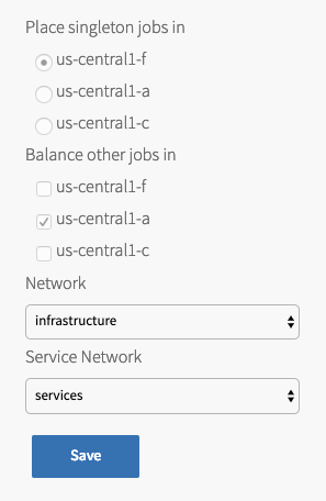
- Under Balance other jobs in, select the AZ for balancing other control plane jobs.
Note: You must specify the Balance other jobs in AZ, but the selection has no effect in the current version of .
- Under Network, select the infrastructure subnet that you created for component VMs, such as the and VMs.
- Under Service Network, select the services subnet that you created for Kubernetes cluster VMs.
- Click Save.
TKGI API
Perform the following steps:
-
Click TKGI API.
-
Under Certificate to secure the TKGI API, provide a certificate and private key pair.
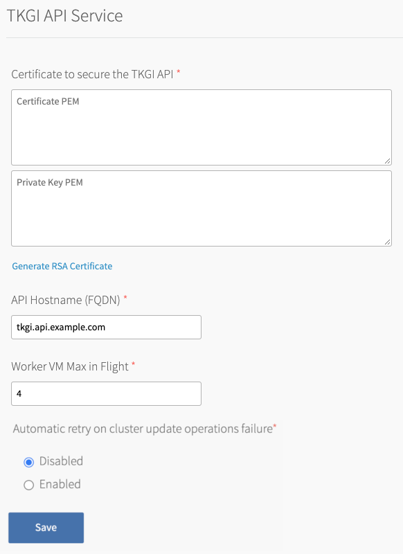
The certificate that you supply must cover the specific subdomain that routes to the TKGI API VM with TLS termination on the ingress. If you use UAA as your OIDC provider, this certificate must be a proper certificate chain and have a SAN field.
Warning: TLS certificates generated for wildcard DNS records only work for a single domain level. For example, a certificate generated for
You can enter your own certificate and private key pair, or have Ops Manager generate one for you.*.tkgi.EXAMPLE.comdoes not permit communication to*.api.tkgi.EXAMPLE.com. If the certificate does not contain the correct FQDN for the TKGI API, calls to the API will fail.
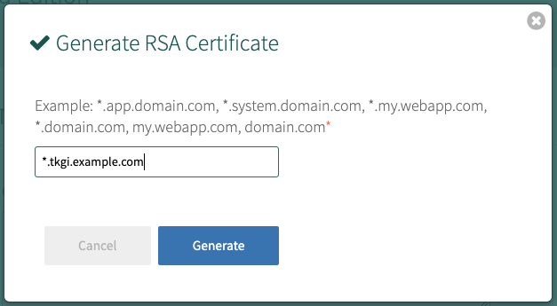
To generate a certificate using Ops Manager:- Click Generate RSA Certificate for a new install or Change to update a previously-generated certificate.
- Enter the domain for your API hostname. This must match the domain you configure under TKGI API > API Hostname (FQDN) below, in the same pane. It can be a standard FQDN or a wildcard domain.
- Click Generate.
- Under API Hostname (FQDN), enter the FQDN that you registered to point to the TKGI API load balancer, such as
api.tkgi.example.com. To retrieve the public IP address or FQDN of the TKGI API load balancer, log in to your IaaS console.Note: The FQDN for the TKGI API must not contain uppercase letters or trailing whitespace.
- Under Worker VM Max in Flight, enter the maximum number of non-canary worker instances to create, update or upgrade in parallel within an availability zone.
This field sets themax_in_flightvariable value. Themax_in_flightsetting limits the number of component instances the TKGI CLI creates or starts simultaneously when runningtkgi create-clusterortkgi update-cluster. By default,max_in_flightis set to4, limiting the TKGI CLI to creating or starting a maximum of four component instances in parallel. - Enable the Automatic retry on cluster update operations failure option to make
tkgi update-clusterretry the cluster update process up to three times if it fails. - Click Save.
Plans
A plan defines a set of resource types used for deploying a cluster.
Activate a Plan
You must first activate and configure Plan 1, and afterwards you can activate up to twelve additional, optional, plans.
To activate and configure a plan, perform the following steps:
- Click the plan that you want to activate.
Note: Plans 11, 12, and 13 support Windows worker-based Kubernetes clusters on vSphere with NSX, and are a beta feature on vSphere with Antrea. To configure a Windows worker plan see Plans in Configuring Windows Worker-Based Kubernetes Clusters for more information.
- Select Active to activate the plan and make it available to developers deploying clusters.
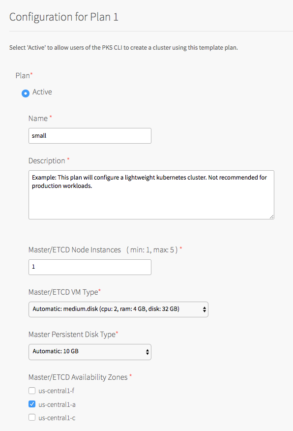
- Under Name, provide a unique name for the plan.
- Under Description, edit the description as needed. The plan description appears in the Services Marketplace, which developers can access by using the TKGI CLI.
- Under Master/ETCD Node Instances, select the default number of Kubernetes control plane/etcd nodes to provision for each cluster. You can enter
1,3, or5.Note: If you deploy a cluster with multiple control plane/etcd node VMs, confirm that you have sufficient hardware to handle the increased load on disk write and network traffic. For more information, see Hardware recommendations in the etcd documentation.
In addition to meeting the hardware requirements for a multi-control plane node cluster, we recommend configuring monitoring for etcd to monitor disk latency, network latency, and other indicators for the health of the cluster. For more information, see Configuring Telegraf in TKGI.WARNING: To change the number of control plane/etcd nodes for a plan, you must ensure that no existing clusters use the plan. Tanzu Kubernetes Grid Integrated Edition does not support changing the number of control plane/etcd nodes for plans with existing clusters.
-
Under Master/ETCD VM Type, select the type of VM to use for Kubernetes control plane/etcd nodes. For more information, including control plane node VM customization options, see the Control Plane Node VM Size section of VM Sizing for Tanzu Kubernetes Grid Integrated Edition Clusters.
-
Under Master Persistent Disk Type, select the size of the persistent disk for the Kubernetes control plane node VM.
-
Under Master/ETCD Availability Zones, select one or more AZs for the Kubernetes clusters deployed by Tanzu Kubernetes Grid Integrated Edition. If you select more than one AZ, Tanzu Kubernetes Grid Integrated Edition deploys the control plane VM in the first AZ and the worker VMs across the remaining AZs. If you are using multiple control plane nodes, deploys the control plane and worker VMs across the AZs in round-robin fashion.
Note: Tanzu Kubernetes Grid Integrated Edition does not support changing the AZs of existing control plane nodes.
- Under Maximum number of workers on a cluster, set the maximum number of Kubernetes worker node VMs that Tanzu Kubernetes Grid Integrated Edition can deploy for each cluster. Enter any whole number in this field.
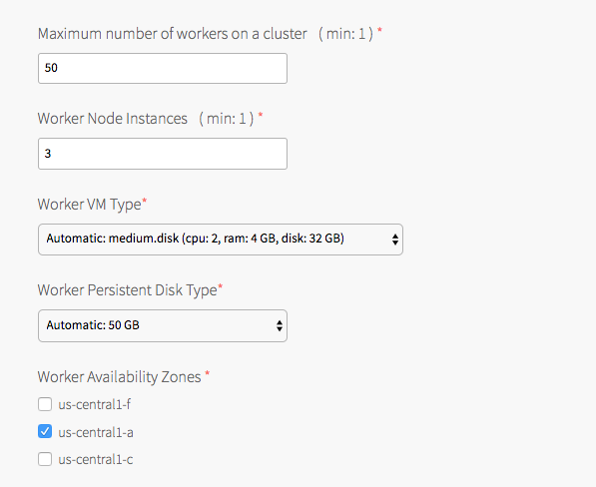
- Under Worker Node Instances, specify the default number of Kubernetes worker nodes the TKGI CLI provisions for each cluster. The Worker Node Instances setting must be less than, or equal to, the Maximum number of workers on a cluster setting.
For high availability, create clusters with a minimum of three worker nodes, or two per AZ if you intend to use PersistentVolumes (PVs). For example, if you deploy across three AZs, you must have six worker nodes. For more information about PVs, see PersistentVolumes in Maintaining Workload Uptime. Provisioning a minimum of three worker nodes, or two nodes per AZ is also recommended for stateless workloads.
For more information about creating clusters, see Creating Clusters.Note: Changing a plan’s Worker Node Instances setting does not alter the number of worker nodes on existing clusters. For information about scaling an existing cluster, see Scale Horizontally by Changing the Number of Worker Nodes Using the TKGI CLI in Scaling Existing Clusters.
- Under Worker VM Type, select the type of VM to use for Kubernetes worker node VMs. For more information, including worker node VM customization options, see Worker Node VM Number and Size in VM Sizing for Tanzu Kubernetes Grid Integrated Edition Clusters.
Note: Tanzu Kubernetes Grid Integrated Edition requires a Worker VM Type with an ephemeral disk size of 32 GB or more.
-
Under Worker Persistent Disk Type, select the size of the persistent disk for the Kubernetes worker node VMs.
-
Under Worker Availability Zones, select one or more AZs for the Kubernetes worker nodes. Tanzu Kubernetes Grid Integrated Edition deploys worker nodes equally across the AZs you select.
-
Under Kubelet customization - system-reserved, enter resource values that Kubelet can use to reserve resources for system daemons. For example,
memory=250Mi, cpu=150m. For more information about system-reserved values, see the Kubernetes documentation.
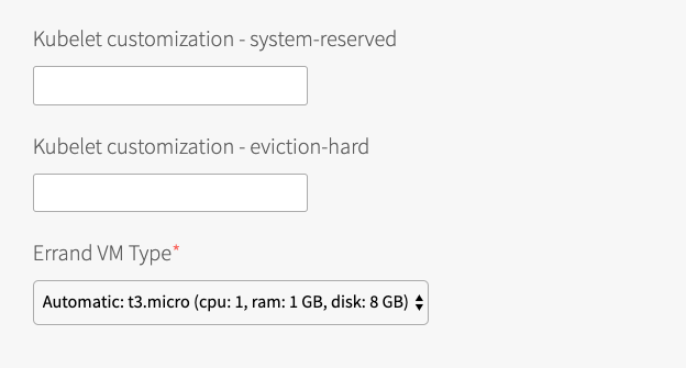
- Under Kubelet customization - eviction-hard, enter threshold limits that Kubelet can use to evict pods when they exceed the limit. Enter limits in the format
EVICTION-SIGNAL=QUANTITY. For example,memory.available=100Mi, nodefs.available=10%, nodefs.inodesFree=5%. For more information about eviction thresholds, see the Kubernetes documentation.WARNING: Use the Kubelet customization fields with caution. If you enter values that are invalid or that exceed the limits the system supports, Kubelet might fail to start. If Kubelet fails to start, you cannot create clusters.
- Under Errand VM Type, select the size of the VM that contains the errand. The smallest instance possible is sufficient, as the only errand running on this VM is the one that applies the Default Cluster App YAML configuration.
- (Optional) Under (Optional) Add-ons - Use with caution, enter additional YAML configuration to add custom workloads to each cluster in this plan. You can specify multiple files using
---as a separator. For more information, see Adding Custom Linux Workloads. - (Optional) Select the Allow Privileged option to allow users to either create Pods with privileged containers or create clusters with resizable persistent volumes using a manually installed vSphere CSI driver. For more information about privileged mode, see Pods in the Kubernetes documentation.
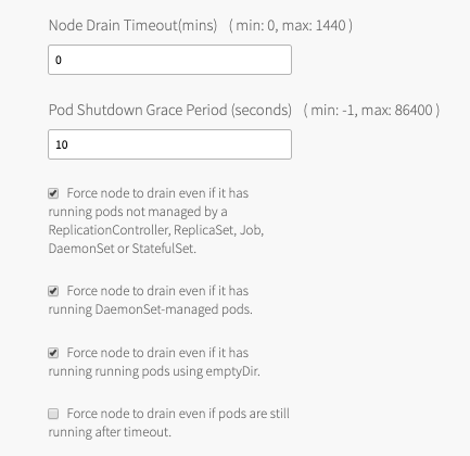
Allow Privileged is not required if clusters use the automatically installed vSphere CSI driver for vSphere CNS. For information about using the automatically installed vSphere CSI driver, see Storage below and Deploying Cloud Native Storage (CNS) on vSphere. - (Optional) Under Node Drain Timeout(mins), enter the timeout in minutes for the node to drain pods. If you set this value to
0, the node drain does not terminate.
-
(Optional) Under Pod Shutdown Grace Period (seconds), enter a timeout in seconds for the node to wait before it forces the pod to terminate. If you set this value to
-1, the default timeout is set to the one specified by the pod. -
(Optional) To configure when the node drains, activate the following:
- Force node to drain even if it has running pods not managed by a ReplicationController, ReplicaSet, Job, DaemonSet or StatefulSet.
- Force node to drain even if it has running DaemonSet-managed pods.
- Force node to drain even if it has running running pods using emptyDir.
- Force node to drain even if pods are still running after timeout.
Warning: If you select Force node to drain even if pods are still running after timeout, the node halts all running workloads on pods. Before enabling this configuration, set Node Drain Timeout to a value greater than
0.For more information about configuring default node drain behavior, see Worker Node Hangs Indefinitely in Troubleshooting.
-
Click Save.
Deactivate a Plan
To deactivate a plan, perform the following steps:
- Click the plan that you want to deactivate.
- Select Inactive.
- Click Save.
Kubernetes Cloud Provider
In the procedure below, you use credentials for vCenter master VMs. You must have provisioned the service account with the correct permissions. For more information, see Create the Master Node Service Account in Preparing vSphere Before Deploying Tanzu Kubernetes Grid Integrated Edition.
To configure your Kubernetes cloud provider settings, follow the procedure below:
- Click Kubernetes Cloud Provider.
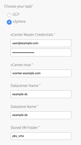
- Under Choose your IaaS, select vSphere.
-
Ensure the values in the following procedure match those in the vCenter Config section of the Ops Manager tile:
- Enter your vCenter Master Credentials. Enter the vCenter Server user name using the format
user@domainname, for example: “[email protected]”. For more information about the master node service account, see Preparing vSphere Before Deploying Tanzu Kubernetes Grid Integrated Edition.
Warning: The vSphere Container Storage Plug-in will not function if you do not specify the domain name for active directory users.
- Enter your vCenter Host. For example,
vcenter-example.com.
Note: The FQDN for the vCenter Server cannot contain uppercase letters.
- Enter your Datacenter Name list. For example,
example-dc, folder-name/dc-name. -
Enter your Datastore Name. For example,
example-ds. Populate Datastore Name with the Persistent Datastore name configured in your BOSH Director tile under vCenter Config > Persistent Datastore Names. Enter only a single Persistent datastore in the Datastore Name field.- The vSphere datastore type must be Datastore. Tanzu Kubernetes Grid Integrated Edition does not support the use of vSphere Datastore Clusters with or without Storage DRS. For more information, see Datastores and Datastore Clusters in the vSphere documentation.
- The Datastore Name is the default datastore used if the Kubernetes cluster
StorageClassdoes not define aStoragePolicy. Do not enter a datastore that is a list of BOSH Job/VMDK datastores. For more information, see PersistentVolume Storage Options on vSphere. - For multi-AZ and multi-cluster environments, your Datastore Name must be a shared Persistent datastore available to each vSphere cluster. Do not enter a datastore that is local to a single cluster. For more information, see PersistentVolume Storage Options on vSphere.
-
Enter the Stored VM Folder so that the persistent stores know where to find the VMs. To retrieve the name of the folder, navigate to your BOSH Director tile, click vCenter Config, and locate the value for VM Folder. The default folder name is
pks_vms.
- Enter your vCenter Master Credentials. Enter the vCenter Server user name using the format
- Click Save.
Networking
To configure networking, do the following:
- Click Networking.
- Under Container Networking Interface, select Antrea.
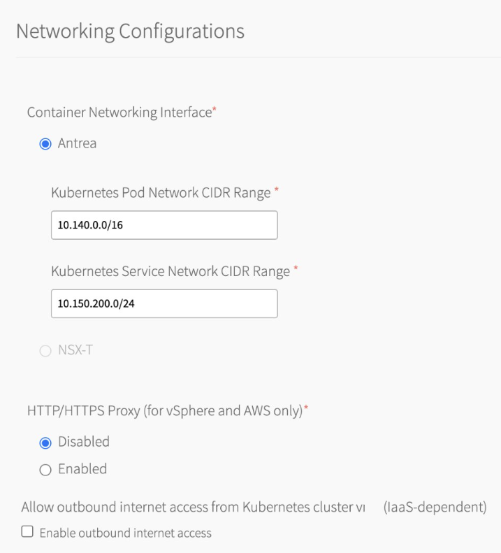 Antrea is the Container Networking Interface (CNI) for TKGI v1.19. Flannel CNI is no longer supported. For more information about Flannel CNI removal, see About Switching from the Flannel CNI to the Antrea CNI in the TKGI 1.18 documentation.
 - (Optional) Enter values for Kubernetes Pod Network CIDR Range and Kubernetes Service Network CIDR Range.
- Ensure that the CIDR ranges do not overlap and have sufficient space for your deployed services.
- Ensure that the CIDR range for the Kubernetes Pod Network CIDR Range is large enough to accommodate the expected maximum number of pods.
- (Optional) Configure Tanzu Kubernetes Grid Integrated Edition to use a proxy.
Production environments can deny direct access to public Internet services and between internal services by placing an HTTP or HTTPS proxy in the network path between Kubernetes nodes and those services.
Configure Tanzu Kubernetes Grid Integrated Edition to use your proxy and activate the following:- TKGI API access to public Internet services and other internal services.
- Tanzu Kubernetes Grid Integrated Edition-deployed Kubernetes nodes access to public Internet services and other internal services.
- Tanzu Kubernetes Grid Integrated Edition Telemetry ability to forward Telemetry data to the CEIP and Telemetry program.
Note: This setting does not set the proxy for running Kubernetes workloads or pods.
-
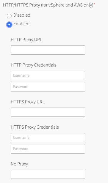
To complete your global proxy configuration for all outgoing HTTP/HTTPS traffic from your Kubernetes clusters, perform the following steps:
- To proxy outgoing HTTP traffic, enter the URL of your HTTP proxy endpoint under HTTP Proxy URL. For example,
http\://myproxy.com:1234. - (Optional) If your outgoing HTTP proxy uses basic authentication, enter the user name and password in the HTTP Proxy Credentials fields.
- To proxy outgoing HTTPS traffic, enter the URL of your HTTP proxy endpoint under HTTPS Proxy URL. For example,
http\://myproxy.com:1234.
Note: Using an HTTPS connection to the proxy server is not supported. HTTP and HTTPS proxy options can only be configured with an HTTP connection to the proxy server. You cannot populate either of the proxy URL fields with an HTTPS URL. The proxy host and port can be different for HTTP and HTTPS traffic, but the proxy protocol must be HTTP.
- (Optional) If your HTTPS proxy uses basic authentication, enter the user name and password in the HTTPS Proxy Credentials fields.
- Under No Proxy, enter the comma-separated list of IP addresses that must bypass the proxy to allow for internal Tanzu Kubernetes Grid Integrated Edition communication.
Include127.0.0.1andlocalhostin the No Proxy list.
Also include the following in the No Proxy list:- Your Tanzu Kubernetes Grid Integrated Edition environment’s CIDRs, such as the service network CIDR where your Tanzu Kubernetes Grid Integrated Edition cluster is deployed, the deployment network CIDR, the node network IP block CIDR, and the pod network IP block CIDR.
- The FQDN of any registry, such as the Harbor API FQDN, or component communicating with Tanzu Kubernetes Grid Integrated Edition, using a hostname instead of an IP address.
- The IP addresses for your NSX Manager, vCenter Server, and all ESXi hosts, if you are upgrading and have an existing proxy configuration for reaching a Docker registry or other external services.
- Any additional IP addresses or domain names that must bypass the proxy.
The No Proxy property for vSphere accepts wildcard domains denoted by a prefixed\*.or..
For example:
127.0.0.1,localhost, *.example1.com, .example2.com, example3.com, 198.51.100.0/24, 203.0.113.0/24, 192.0.2.0/24 - Your Tanzu Kubernetes Grid Integrated Edition environment’s CIDRs, such as the service network CIDR where your Tanzu Kubernetes Grid Integrated Edition cluster is deployed, the deployment network CIDR, the node network IP block CIDR, and the pod network IP block CIDR.
Note: By default the
10.100.0.0/8and10.200.0.0/8IP address ranges,.internal,.svc,.svc.cluster.local,.svc.cluster, and your Tanzu Kubernetes Grid Integrated Edition FQDN are not proxied. This allows internal Tanzu Kubernetes Grid Integrated Edition communication.
Do not use the_character in the No Proxy field. Entering an underscore character in this field can cause upgrades to fail.
Because some jobs in the VMs accept\*.as a wildcard, while others only accept., we recommend that you define a wildcard domain using both of them. For example, to denoteexample.comas a wildcard domain, add both\*.example.comandexample.comto the No Proxy property. - To proxy outgoing HTTP traffic, enter the URL of your HTTP proxy endpoint under HTTP Proxy URL. For example,
-
Under Allow outbound internet access from Kubernetes cluster vms (IaaS-dependent), ignore the Enable outbound internet access check box.
- Click Save.
UAA
To configure the UAA server:
- Click UAA.
-
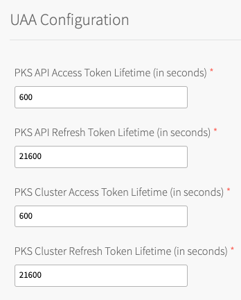
Under TKGI API Access Token Lifetime, enter a time in seconds for the TKGI API access token lifetime. This field defaults to
600.
-
Under TKGI API Refresh Token Lifetime, enter a time in seconds for the TKGI API refresh token lifetime. This field defaults to
21600. - Under TKGI Cluster Access Token Lifetime, enter a time in seconds for the cluster access token lifetime. This field defaults to
600. - Under TKGI Cluster Refresh Token Lifetime, enter a time in seconds for the cluster refresh token lifetime. This field defaults to
21600.Note: VMware recommends using the default UAA token timeout values. By default, access tokens expire after ten minutes and refresh tokens expire after six hours.
- Under Configure created clusters to use UAA as the OIDC provider, select Enabled or Disabled. This is a global default setting for TKGI-provisioned clusters. For more information, see OIDC Provider for Kubernetes Clusters.
To configure Tanzu Kubernetes Grid Integrated Edition to use UAA as the OIDC provider:- Under Configure created clusters to use UAA as the OIDC provider, select Enabled.
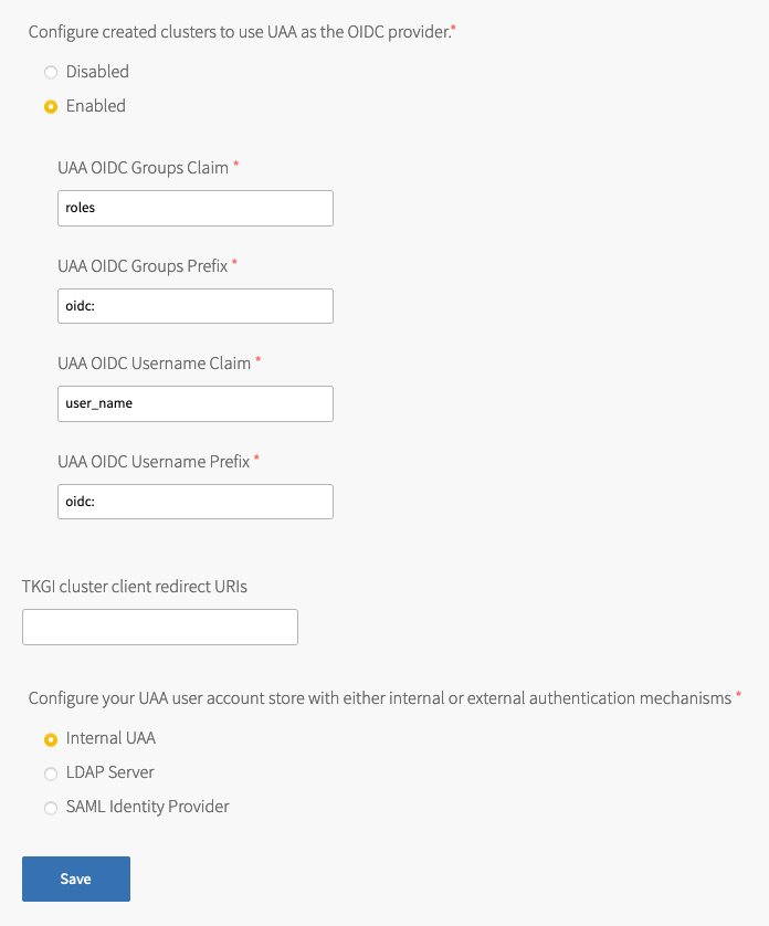
- For UAA OIDC Groups Claim, enter the name of your groups claim. This is used to set a user’s group in the JSON Web Token (JWT) claim. The default value is
roles. - For UAA OIDC Groups Prefix, enter a prefix for your groups claim. This prevents conflicts with existing names. For example, if you enter the prefix
oidc:, UAA creates a group name likeoidc:developers. The default value isoidc:. - For UAA OIDC Username Claim, enter the name of your user name claim. This is used to set a user’s user name in the JWT claim. The default value is
user_name. Depending on your provider, you can enter claims besidesuser_name, likeemailorname. - For UAA OIDC Username Prefix, enter a prefix for your user name claim. This prevents conflicts with existing names. For example, if you enter the prefix
oidc:, UAA creates a user name likeoidc:admin. The default value isoidc:.Warning: VMware recommends adding OIDC prefixes to prevent users and groups from gaining unintended cluster privileges. If you change the above values for a pre-existing Tanzu Kubernetes Grid Integrated Edition installation, you must change any existing role bindings that bind to a user name or group. If you do not change your role bindings, developers cannot access Kubernetes clusters. For instructions, see Managing Cluster Access and Permissions.
- Under Configure created clusters to use UAA as the OIDC provider, select Enabled.
- (Optional) For TKGI cluster client redirect URIs, enter one or more comma-delimited UAA redirect URIs. Configure TKGI cluster client redirect URIs to assign persistent UAA
cluster_clientredirect_uriURIs to your clusters. UAA redirect URIs configured in the TKGI cluster client redirect URIs field persist through cluster updates and TKGI upgrades. - Select one of the following options:
- To use an internal user account store for UAA, select Internal UAA. Click Save and continue to (Optional) Host Monitoring.
- To use LDAP for UAA, select LDAP Server and continue to Connecting Tanzu Kubernetes Grid Integrated Edition to an LDAP Server.
- To use SAML for UAA, select SAML Identity Provider and continue to Connecting Tanzu Kubernetes Grid Integrated Edition to a SAML Identity Provider.
(Optional) Host Monitoring
In Host Monitoring, you can configure monitoring of nodes and VMs using Syslog, VMware vRealize Log Insight (vRLI) Integration, or Telegraf.
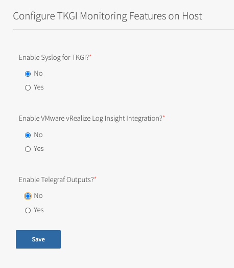
You can configure one or more of the following:
- Syslog: To configure Syslog, see Syslog below. Syslog forwards log messages from all BOSH-deployed VMs to a syslog endpoint.
- VMware vRealize Log Insight (vRLI) Integration: To configure VMware vRealize Log Insight (vRLI) Integration, see VMware vRealize Log Insight Integration below. The vRLI integration pulls logs from all BOSH jobs and containers running in the cluster, including node logs from core Kubernetes and BOSH processes, Kubernetes event logs, and pod
stdoutandstderr. - Telegraf: To configure Telegraf, see Configuring Telegraf in TKGI. The Telegraf agent sends metrics from TKGI API, control plane node, and worker node VMs to a monitoring service, such as Wavefront or Datadog.
For more information about these components, see Monitoring TKGI and TKGI-Provisioned Clusters.
Syslog
To configure Syslog for all BOSH-deployed VMs in Tanzu Kubernetes Grid Integrated Edition:
- Click Host Monitoring.
- Under Enable Syslog for TKGI, select Yes.
- Under Address, enter the destination syslog endpoint.
- Under Port, enter the destination syslog port.
- Under Transport Protocol, select a transport protocol for log forwarding.
- (Optional) To enable TLS encryption during log forwarding, complete the following steps:
- Ensure Enable TLS is selected.
Note: Logs might contain sensitive information, such as cloud provider credentials. VMware recommends that you enable TLS encryption for log forwarding.
- Under Permitted Peer, provide the accepted fingerprint (SHA1) or name of remote peer. For example,
*.YOUR-LOGGING-SYSTEM.com. - Under TLS Certificate, provide a TLS certificate for the destination syslog endpoint.
Note: You do not need to provide a new certificate if the TLS certificate for the destination syslog endpoint is signed by a Certificate Authority (CA) in your BOSH certificate store.
- Ensure Enable TLS is selected.
- (Optional) Under Max Message Size, enter a maximum message size for logs that are forwarded to a syslog endpoint. By default, the Max Message Size field is 10,000 characters.
- (Optional) Under Custom Rsyslog Configuration, enter your RSyslog rules configuration using RainerScript syntax. For more information, see RainerScript in the RSyslog documentation. For example RSyslog rule configurations, see Example Custom Rules in the Syslog BOSH GitHub repository.
- Click Save.
VMware vRealize Log Insight Integration
Note: Before you configure the vRLI integration, you must have a vRLI license and vRLI must be installed, running, and available in your environment. You need to provide the live instance address during configuration. For instructions and additional information, see the vRealize Log Insight documentation.
By default, vRLI logging is deactivated. To configure vRLI logging:- Under Enable VMware vRealize Log Insight Integration?, select Yes.
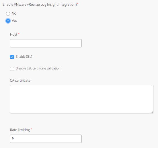
- Under Host, enter the IP address or FQDN of the vRLI host.
- (Optional) Select the Enable SSL? check box to encrypt the logs being sent to vRLI using SSL.
- Choose one of the following SSL certificate validation options:
- To skip certificate validation for the vRLI host, select the Disable SSL certificate validation check box. Select this option if you are using a self-signed certificate in order to simplify setup for a development or test environment.
Note: Deactivating certificate validation is not recommended for production environments.
- To enable certificate validation for the vRLI host, clear the Disable SSL certificate validation check box.
- To skip certificate validation for the vRLI host, select the Disable SSL certificate validation check box. Select this option if you are using a self-signed certificate in order to simplify setup for a development or test environment.
- (Optional) If your vRLI certificate is not signed by a trusted CA root or other well known certificate, enter the certificate in the CA certificate field. Locate the PEM of the CA used to sign the vRLI certificate, copy the contents of the certificate file, and paste them into the field. Certificates must be in PEM-encoded format.
- Under Rate limiting, enter a time in milliseconds to change the rate at which logs are sent to the vRLI host. The rate limit specifies the minimum time between messages before the fluentd agent begins to drop messages. The default value
0means that the rate is not limited, which suffices for many deployments.
Note: If your deployment is generating a high volume of logs, you can increase this value to limit network traffic. Consider starting with a lower value, such as
10, then tuning to optimize for your deployment. A large number might result in dropping too many log entries. - Click Save. These settings apply to any clusters created after you have saved these configuration settings and clicked Apply Changes. If the Upgrade all clusters errand has been enabled, these settings are also applied to existing clusters.
Note: The Tanzu Kubernetes Grid Integrated Edition tile does not validate your vRLI configuration settings. To verify your setup, look for log entries in vRLI.
(Optional) In-Cluster Monitoring
In In-Cluster Monitoring, you can configure one or more observability components and integrations that run in Kubernetes clusters and capture logs and metrics about your workloads. For more information, see Monitoring Workers and Workloads.
To configure in-cluster monitoring:
- To configure Wavefront, see Wavefront.
- To configure cAdvisor, see VMware vRealize Operations Management Pack for Container Monitoring.
-
To configure sink resources, see:
You can enable both log and metric sink resources or only one of them.
Wavefront
You can monitor Kubernetes clusters and pods metrics externally using the integration with Wavefront by VMware.
Note: Before you configure Wavefront integration, you must have an active Wavefront account and access to a Wavefront instance. You provide your Wavefront access token during configuration. For additional information, see the Wavefront documentation.
To use Wavefront with Windows worker-based clusters, developers must install Wavefront to their clusters manually, using Helm.
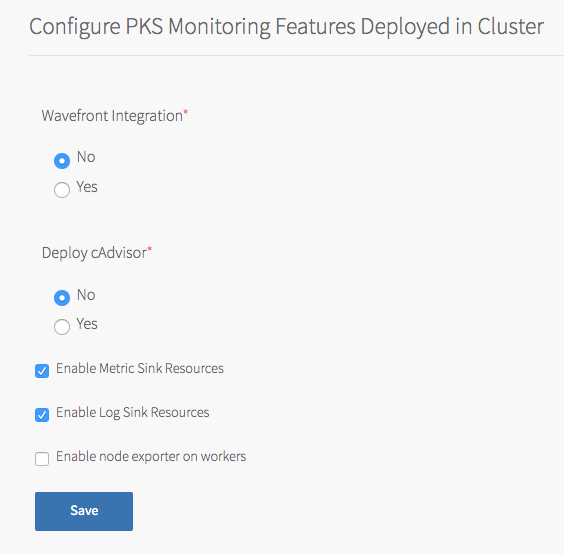
To enable and configure Wavefront monitoring:
- In the Tanzu Kubernetes Grid Integrated Edition tile, select In-Cluster Monitoring.
- Under Wavefront Integration, select Yes.
- Under Wavefront URL, enter the URL of your Wavefront subscription. For example:
https://try.wavefront.com/api - Under Wavefront Access Token, enter the API token for your Wavefront subscription.
- (Optional) For installations that require a proxy server for outbound Internet access, enable access by entering values for HTTP Proxy Host, HTTP Proxy Port, Proxy username, and Proxy password.
- Click Save.
The Tanzu Kubernetes Grid Integrated Edition tile does not validate your Wavefront configuration settings. To verify your setup, look for cluster and pod metrics in Wavefront.
VMware vRealize Operations Management Pack for Container Monitoring
You can monitor Tanzu Kubernetes Grid Integrated Edition Kubernetes clusters with VMware vRealize Operations Management Pack for Container Monitoring.
To integrate Tanzu Kubernetes Grid Integrated Edition with VMware vRealize Operations Management Pack for Container Monitoring, you must deploy a container running cAdvisor in your TKGI deployment.
cAdvisor is an open source tool that provides monitoring and statistics for Kubernetes clusters.
To deploy a cAdvisor container:
- Select In-Cluster Monitoring.
- Under Deploy cAdvisor, select Yes.
- Click Save.
For more information about integrating this type of monitoring with TKGI, see the VMware vRealize Operations Management Pack for Container Monitoring User Guide and Release Notes in the VMware documentation.
Metric Sink Resources
You can configure TKGI-provisioned clusters to send Kubernetes node metrics and pod metrics to metric sinks. For more information about metric sink resources and what to do after you enable them in the tile, see Sink Resources in Monitoring Workers and Workloads.
To enable clusters to send Kubernetes node metrics and pod metrics to metric sinks:
- In In-Cluster Monitoring, select Enable Metric Sink Resources. If you enable this check box, Tanzu Kubernetes Grid Integrated Edition deploys Telegraf as a
DaemonSet, a pod that runs on each worker node in all your Kubernetes clusters. -
(Optional) To enable Node Exporter to send worker node metrics to metric sinks of kind
ClusterMetricSink, select Enable node exporter on workers. If you enable this check box, Tanzu Kubernetes Grid Integrated Edition deploys Node Exporter as aDaemonSet, a pod that runs on each worker node in all your Kubernetes clusters.For instructions on how to create a metric sink of kind
ClusterMetricSinkfor Node Exporter metrics, see Create a ClusterMetricSink Resource for Node Exporter Metrics in Creating and Managing Sink Resources. - Click Save.
Log Sink Resources
You can configure TKGI-provisioned clusters to send Kubernetes API events and pod logs to log sinks. For more information about log sink resources and what to do after you enable them in the tile, see Sink Resources in Monitoring Workers and Workloads.
To enable clusters to send Kubernetes API events and pod logs to log sinks:
- Select Enable Log Sink Resources. If you enable this check box, Tanzu Kubernetes Grid Integrated Edition deploys Fluent Bit as a
DaemonSet, a pod that runs on each worker node in all your Kubernetes clusters. -
(Optional) To increase the Fluent Bit Pod memory limit, enter a value greater than 100 in the Fluent-bit container memory limit(Mi) field.
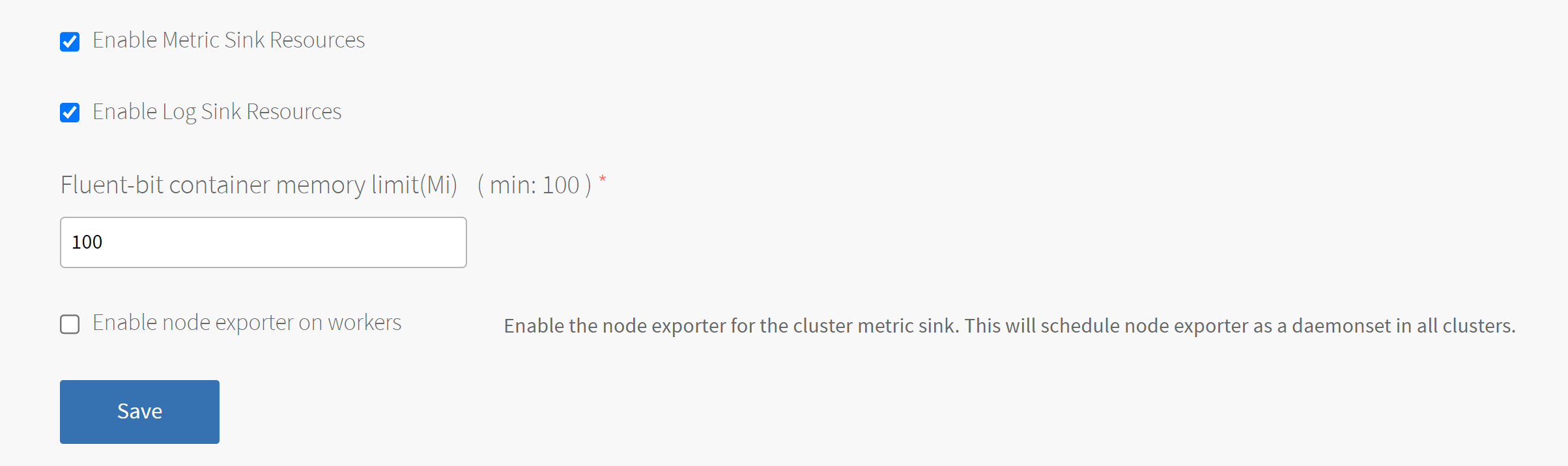
-
Click Save.
Tanzu Mission Control
Tanzu Mission Control integration lets you monitor and manage Tanzu Kubernetes Grid Integrated Edition clusters from the Tanzu Mission Control console, which makes the Tanzu Mission Control console a single point of control for all Kubernetes clusters. For more information about Tanzu Mission Control, see the VMware Tanzu Mission Control home page.
To integrate Tanzu Kubernetes Grid Integrated Edition with Tanzu Mission Control:
-
Confirm that the TKGI API VM has internet access and can connect to
cna.tmc.cloud.vmware.comand the other outbound URLs listed in the What Happens When You Attach a Cluster section of the Tanzu Mission Control Product documentation. -
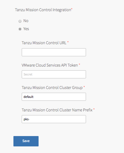
Navigate to the Tanzu Kubernetes Grid Integrated Edition tile > the Tanzu Mission Control pane and select Yes under Tanzu Mission Control Integration.
-
Configure the fields below:
- Tanzu Mission Control URL: Enter the Org URL of your Tanzu Mission Control subscription, without a trailing slash (
/). For example,YOUR-ORG.tmc.cloud.vmware.com. - VMware Cloud Services API token: Enter your API token to authenticate with VMware Cloud Services APIs. You can retrieve this token by logging in to VMware Cloud Services and viewing your account information.
-
Tanzu Mission Control Cluster Group: Enter the name of a Tanzu Mission Control cluster group.
The name can bedefaultor another value, depending on your role and access policy:Org Memberusers in VMware cloud services have aservice.adminrole in Tanzu Mission Control. These users:- By default, can create and attach clusters only in the
defaultcluster group. - Can create and attach clusters to other cluster groups after an
organization.adminuser grants them theclustergroup.adminorclustergroup.editrole for those groups.
- By default, can create and attach clusters only in the
-
Org Ownerusers in VMware cloud services haveorganization.adminpermissions in Tanzu Mission Control. These users:- Can create cluster groups.
- Can grant
clustergrouproles toservice.adminusers through the Tanzu Mission Control Access Policy view.
For more information about role and access policy, see Access Control in the VMware Tanzu Mission Control Product documentation.
- Tanzu Mission Control Cluster Name Prefix: Enter a name prefix for identifying the Tanzu Kubernetes Grid Integrated Edition clusters in Tanzu Mission Control.
- Tanzu Mission Control URL: Enter the Org URL of your Tanzu Mission Control subscription, without a trailing slash (
- Click Save.
Warning: After the Tanzu Kubernetes Grid Integrated Edition tile is deployed with a configured cluster group, the cluster group cannot be updated.
Note: When you upgrade your Kubernetes clusters and have Tanzu Mission Control integration enabled, existing clusters will be attached to Tanzu Mission Control.
VMware CEIP
Tanzu Kubernetes Grid Integrated Edition-provisioned clusters send usage data to the TKGI control plane for storage. The VMware Customer Experience Improvement Program (CEIP) provides the option to also send the cluster usage data to VMware to improve customer experience.
To configure Tanzu Kubernetes Grid Integrated Edition CEIP Program settings:
- Click CEIP.
- Review the information about the CEIP.
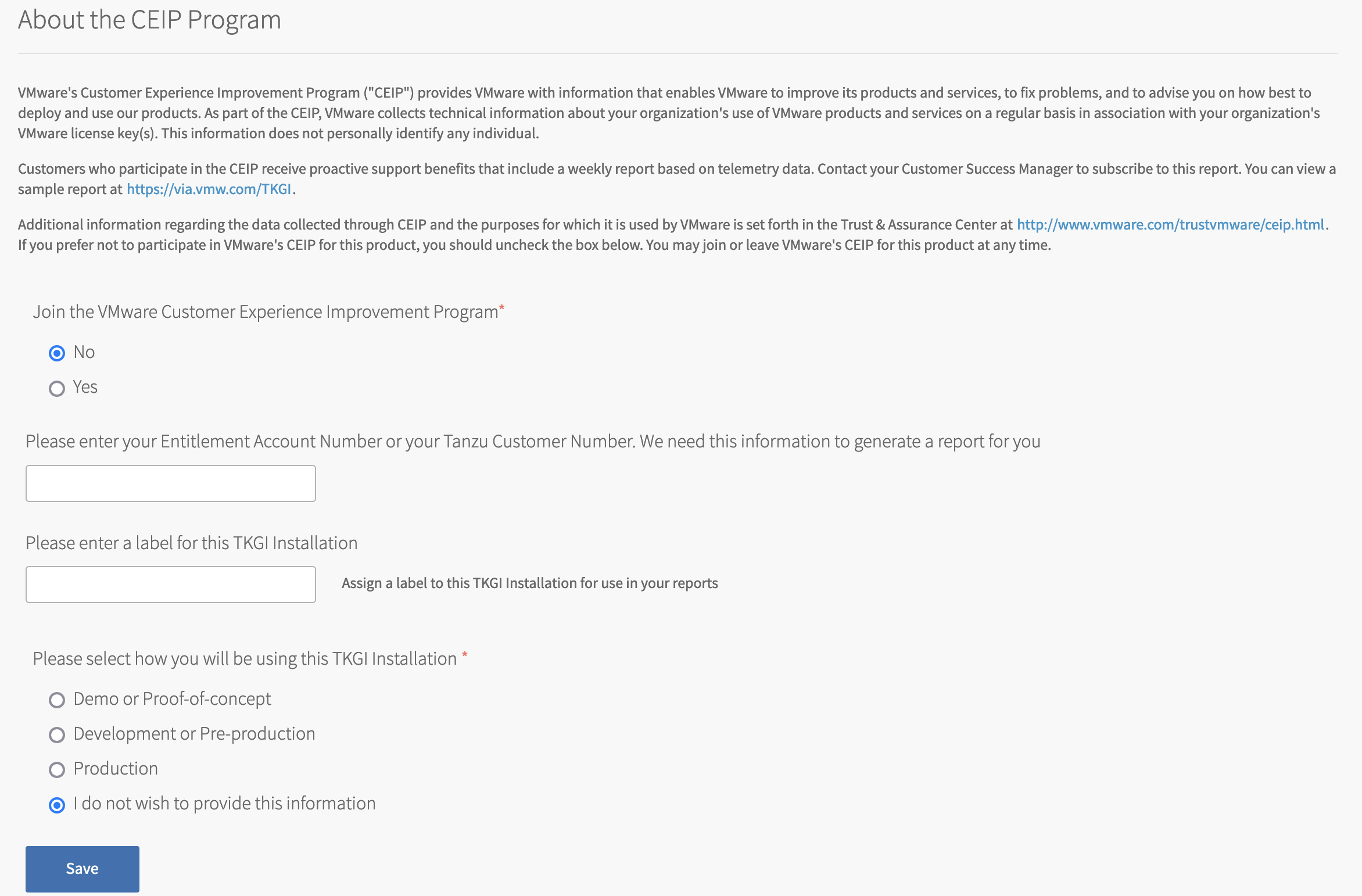
View a larger version of this image. - If you wish to participate in CEIP, select Yes. Otherwise, select No.
- If you selected the Yes, complete the following:
- (Optional) Enter your entitlement account number or Tanzu customer number. If you are a VMware customer, you can find your entitlement account number in your Account Summary on my.vmware.com. If you are a Pivotal customer, you can find your Pivotal Customer Number in your Pivotal Order Confirmation email.
- (Optional) Enter a descriptive name for your TKGI installation. The label you assign to this installation will be used in CEIP reports to identify the environment.
- To provide information about the purpose for this installation, select an option.

- Click Save.
Storage
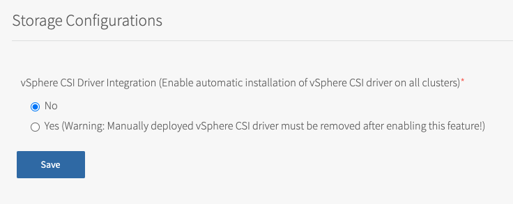
In Storage Configurations, you can configure vSphere CNS settings.
To configure vSphere CNS:
-
Select Storage.
-
(Optional) To enable automatic installation of the vSphere CSI driver on all clusters, select Yes.
Warning: If you have existing clusters with a manually deployed vSphere CSI driver, you must remove the manually deployed driver after enabling this feature. For more information, see Deploying Cloud Native Storage (CNS) on vSphere.
Errands
Errands are scripts that run at designated points during an installation.
To configure which post-deploy and pre-delete errands run for Tanzu Kubernetes Grid Integrated Edition:
- Make a selection in the dropdown next to each errand.
Note: We recommend that you use the default settings for all errands except for the Run smoke tests errand.
-
(Optional) Set the Run smoke tests errand to On.
The Smoke Test errand smoke tests the TKGI upgrade by creating and deleting a test Kubernetes cluster. If test cluster creation or deletion fails, the errand fails, and the installation of the TKGI tile halts.
The errand uses the TKGI CLI to create the test cluster configured using the configuration settings on the TKGI tile.
-
(Optional) To ensure that all of your cluster VMs are patched, configure the Upgrade all clusters errand errand to On.
Updating the Tanzu Kubernetes Grid Integrated Edition tile with a new Linux stemcell and the Upgrade all clusters errand enabled triggers the rolling of every Linux VM in each Kubernetes cluster. Similarly, updating the Tanzu Kubernetes Grid Integrated Edition tile with a new Windows stemcell triggers the rolling of every Windows VM in your Kubernetes clusters.
Note: VMware recommends that you review the Broadcom Support metadata and confirm stemcell version compatibility before using the Broadcom Support APIs to update the stemcells in your automated pipeline. See Retrieve Product Version Compatibilities from the Tanzu API in the Broadcom Support KB.
Resource Config
To modify the resource configuration of Tanzu Kubernetes Grid Integrated Edition, follow the steps below:
- Select Resource Config.
-
For each job, review the Automatic values in the following fields:
- INSTANCES: Tanzu Kubernetes Grid Integrated Edition defaults to the minimum configuration. If you want a highly available configuration (beta), scale the number of VM instances as follows:
- To configure your Tanzu Kubernetes Grid Integrated Edition database for high availability (beta), increase the INSTANCES value for TKGI Database to
3. - To configure your Tanzu Kubernetes Grid Integrated Edition API and UAA for high availability (beta), increase the INSTANCES value for TKGI API to
2or more.Warning: High availability mode is a beta feature. Do not scale your TKGI API or TKGI Database to more than one instance in production environments.
- To configure your Tanzu Kubernetes Grid Integrated Edition database for high availability (beta), increase the INSTANCES value for TKGI Database to
- VM TYPE: By default, the TKGI Database and TKGI API jobs are set to the same Automatic VM type. If you want to adjust this value, we recommend that you select the same VM type for both jobs.
Note: The Automatic VM TYPE values match the recommended resource configuration for the TKGI API and TKGI Database jobs.
- PERSISTENT DISK TYPE: By default, the TKGI Database and TKGI API jobs are set to the same persistent disk type. If you want to adjust this value, you can change the persistent disk type for each of the jobs independently. Using the same persistent disk type for both jobs is not required.
- INSTANCES: Tanzu Kubernetes Grid Integrated Edition defaults to the minimum configuration. If you want a highly available configuration (beta), scale the number of VM instances as follows:
-
Under each job, leave NSX CONFIGURATION and NSX-V CONFIGURATION blank.
Warning: To avoid workload downtime, use the resource configuration recommended in About Tanzu Kubernetes Grid Integrated Edition Upgrades and Maintaining Workload Uptime.
Step 3: Apply Changes
- Return to the Ops Manager Installation Dashboard.
- Click Review Pending Changes. Select the product that you intend to deploy and review the changes. For more information, see Reviewing Pending Product Changes.
- Click Apply Changes.
Next Installation Step
To configure the TKGI API load balancer, follow the instructions in Configure TKGI API Load Balancer.
