


VMware Tanzu for Kubernetes Operations on VMware Cloud on AWS Reference Design
Tanzu for Kubernetes Operations simplifies operating Kubernetes for multi-cloud deployment by centralizing management and governance for clusters and teams across on-premises, public clouds, and edge. Tanzu for Kubernetes Operations delivers an open source aligned Kubernetes distribution with consistent operations and management to support infrastructure and application modernization.
This document lays out a reference design for deploying VMware Tanzu for Kubernetes Operations on VMware Cloud on AWS.
NoteThe scope of this document is limited to Tanzu Kubernetes Grid (multi-cloud), which is a customer-managed solution.
The following reference design is based on the architecture and components described in VMware Tanzu for Kubernetes Operations Reference Architecture.

Supported Component Matrix
The following table provides the component versions and interoperability matrix supported with the reference design:
| Software Components | Version |
|---|---|
| Tanzu Kubernetes Grid | 2.3.0 |
| VMC on AWS SDDC Version | 1.18 and later |
| NSX Advanced Load Balancer | 22.1.2 |
For the latest information about which software versions can be used together, check the Interoperability Matrix here.
Benefits of Running VMware Tanzu on VMware Cloud on AWS
VMware Cloud on AWS enables your IT and operations teams to add value to your investments in AWS by extending your on-premises VMware vSphere environments to the AWS cloud. VMware Cloud on AWS is an integrated cloud offering jointly developed by Amazon Web Services (AWS) and VMware. It is optimized to run on dedicated, elastic, bare-metal Amazon Elastic Compute Cloud (Amazon EC2) infrastructure and supported by VMware and its partners. For more information about VMware Cloud on AWS, see VMware Cloud on AWS Documentation.
VMware Cloud on AWS enables the following:
- Cloud Migrations
- Data Center Extension
- Disaster Recovery
- Next Generation Applications
By running VMware Tanzu within the same infrastructure as the general VM workloads enabled by the first three use cases, organizations can start their next generation application modernization strategy immediately without incurring additional cost. For example, SDDC spare capacity can be used to run Tanzu Kubernetes Grid to enable next generation application modernization, or compute capacity not used by disaster recovery can be used for Tanzu Kubernetes Grid clusters.
The following additional benefits are enabled by the Elastic Network Interface that connects the VMware Cloud on AWS SDDC to the AWS services within the Amazon VPC:
- Enable developers to modernize existing enterprise apps with AWS cloud capabilities and services.
- Integrate modern application tools and frameworks to develop next generation applications.
- Remove egress charges as all traffic is internal of the Amazon availability zone.
Tanzu Kubernetes Grid Components
VMware Tanzu Kubernetes Grid (TKG) provides organizations with a consistent, upstream-compatible, regional Kubernetes substrate that is ready for end-user workloads and ecosystem integrations. You can deploy Tanzu Kubernetes Grid across software-defined datacenters (SDDC) and public cloud environments, including vSphere, Microsoft Azure, and Amazon EC2.
Tanzu Kubernetes Grid comprises the following components:
- Management Cluster - A management cluster is the first element that you deploy when you create a Tanzu Kubernetes Grid instance. The management cluster is a Kubernetes cluster that performs the role of the primary management and operational center for the Tanzu Kubernetes Grid instance. The management cluster is purpose-built for operating the platform and managing the lifecycle of Tanzu Kubernetes clusters.
- Tanzu Kubernetes Cluster - Tanzu Kubernetes clusters are the Kubernetes clusters in which your application workloads run. These clusters are also referred to as workload clusters. Tanzu Kubernetes clusters can run different versions of Kubernetes, depending on the needs of the applications they run.
- Shared Services Cluster - Each Tanzu Kubernetes Grid instance can have only one shared services cluster. You deploy this cluster only if you intend to deploy shared services such as Contour and Harbor.
- ClusterClass API - Tanzu Kubernetes Grid 2 functions through the creation of a management Kubernetes cluster which holds ClusterClass API. The ClusterClass API then interacts with the infrastructure provider to service workload Kubernetes cluster lifecycle requests. The earlier primitives of Tanzu Kubernetes Clusters will still exist for Tanzu Kubernetes Grid 1.X. A new feature has been introduced as a part of Cluster API called ClusterClass which reduces the need for redundant templating and enables powerful customization of clusters. The whole process for creating a cluster using ClusterClass is the same as before but with slightly different parameters.
- Tanzu Kubernetes Cluster Plans - A cluster plan is a blueprint that describes the configuration with which to deploy a Tanzu Kubernetes cluster. It provides a set of configurable values that describe settings like the number of control plane machines, worker machines, VM types, and so on.
The current release of Tanzu Kubernetes Grid provides two default templates, dev and prod.
- Tanzu Kubernetes Grid Instance - A Tanzu Kubernetes Grid instance is the full deployment of Tanzu Kubernetes Grid, including the management cluster, the workload clusters, and the shared services cluster that you configure.
- Tanzu CLI - A command-line utility that provides the necessary commands to build and operate Tanzu management and Tanzu Kubernetes clusters.
-
Carvel Tools - Carvel is an open-source suite of reliable, single-purpose, composable tools that aid in building, configuring, and deploying applications to Kubernetes. Tanzu Kubernetes Grid uses the following Carvel tools:
- ytt - A command-line tool for templating and patching YAML files. You can also use ytt to collect fragments and piles of YAML into modular chunks for reuse.
- kapp - The application deployment CLI for Kubernetes. It allows you to install, upgrade, and delete multiple Kubernetes resources as one application.
- kbld - An image-building and resolution tool.
- imgpkg - A tool that enables Kubernetes to store configurations and the associated container images as OCI images, and to transfer these images.
- yq - A lightweight and portable command-line YAML, JSON, and XML processor.
yqusesjq-like syntax but works with YAML files as well as with JSON and XML.
-
Bootstrap Machine - The bootstrap machine is the laptop, host, or server on which you download and run the Tanzu CLI. This is where the initial bootstrapping of a management cluster occurs before it is pushed to the platform where it will run.
- Tanzu Kubernetes Grid Installer - The Tanzu Kubernetes Grid installer is a graphical wizard that you launch by running the
tanzu management-cluster create --uicommand. The installer wizard runs locally on the bootstrap machine and provides a user interface to guide you through the process of deploying a management cluster.
Tanzu Kubernetes Grid Storage
Many storage options are available and Kubernetes is agnostic about which option you choose.
For Kubernetes stateful workloads, Tanzu Kubernetes Grid installs the vSphere Container Storage interface (vSphere CSI) to provision Kubernetes persistent volumes for pods automatically. While the default vSAN storage policy can be used, site reliability engineers (SREs) and administrators should evaluate the needs of their applications and craft a specific vSphere Storage Policy. vSAN storage policies describe classes of storage such as SSD and NVME, as well as cluster quotas.
In vSphere 7u1+ environments with vSAN, the vSphere CSI driver for Kubernetes also supports creating NFS File Volumes, which support ReadWriteMany access modes. This allows for provisioning volumes which can be read and written from multiple pods simultaneously. To support this, the vSAN File Service must be enabled.
You can also use other types of vSphere datastores. There are Tanzu Kubernetes Grid Cluster Plans that operators can define to use a certain vSphere datastore when creating new workload clusters. All developers would then have the ability to provision container-backed persistent volumes from that underlying datastore.
| Decision ID | Design Decision | Design Justification | Design Implications |
|---|---|---|---|
| TKO-STG-001 | Use vSAN storage for TKO | VMC on AWS come with default vSAN storage. | NA |
While the default vSAN storage policy can be used, administrators should evaluate the needs of their applications and craft a specific vSphere Storage Policy.

Starting with vSphere 7.0 environments with vSAN, the vSphere CSI driver for Kubernetes also supports the creation of NFS File Volumes, which support ReadWriteMany access modes. This allows for provisioning volumes, which can be read and written from multiple pods simultaneously. To support this, you must enable vSAN File Service.
Tanzu Kubernetes Clusters Networking
A Tanzu Kubernetes cluster provisioned by the Tanzu Kubernetes Grid supports two Container Network Interface (CNI) options:
Both are open-source software that provide networking for cluster pods, services, and ingress.
When you deploy a Tanzu Kubernetes cluster using Tanzu Mission Control or Tanzu CLI, Antrea CNI is automatically enabled in the cluster. To provision a Tanzu Kubernetes cluster using a non-default CNI, see the following instructions:
Each CNI is suitable for a different use case. The following table lists some common use cases for the three CNIs that Tanzu Kubernetes Grid supports. This table helps you select the most appropriate CNI for your Tanzu Kubernetes Grid implementation.
| CNI | Use Case | Pros and Cons |
|---|---|---|
| Antrea | Enable Kubernetes pod networking with IP overlay networks using VXLAN or Geneve for encapsulation. Optionally encrypt node-to-node communication using IPSec packet encryption. Antrea supports advanced network use cases like kernel bypass and network service mesh. |
Pros - Antrea leverages Open vSwitch as the networking data plane. Open vSwitch supports both Linux and Windows. - VMware supports the latest conformant Kubernetes and stable releases of Antrea. |
| Calico | Calico is used in environments where factors like network performance, flexibility, and power are essential. For routing packets between nodes, Calico leverages the BGP routing protocol instead of an overlay network. This eliminates the need to wrap packets with an encapsulation layer, resulting in increased network performance for Kubernetes workloads. |
Pros - Support for Network Policies - High network performance - SCTP support Cons - No multicast support |
| Multus | Multus CNI can give multiple interfaces per each Kubernetes pod. Using Multus CRDs, you can specify which pods get which interfaces and allow different interfaces depending on the use case. | Pros - Separation of data/control planes. - Separate security policies can be used for separate interfaces. - Supports SR-IOV, DPDK, OVS-DPDK, and VPP workloads in Kubernetes with both cloud-native and NFV-based applications in Kubernetes. |
Tanzu Kubernetes Grid Infrastructure Networking
You can deploy Tanzu Kubernetes Grid on various networking stacks, including:
- VMware NSX-T Data Center Networking.
- vSphere Networking (VDS) with NSX Advanced Load Balancer.
NoteThe scope of this document is limited to VMware NSX-T Data Center Networking with NSX Advanced Load Balancer.
Tanzu Kubernetes Grid on NSX-T Networking with NSX Advanced Load Balancer
When deployed on VMware NSX-T Networking, Tanzu Kubernetes Grid uses the NSX-T logical segments and gateways to provide connectivity to Kubernetes control plane VMs, worker nodes, services, and applications. All hosts from the cluster where Tanzu Kubernetes clusters are deployed are configured as NSX-T Transport nodes, which provide network connectivity to the Kubernetes environment.
You can configure NSX Advanced Load Balancer in Tanzu Kubernetes Grid as:
- A load balancer for workloads in the clusters that are deployed on vSphere.
- The L7 ingress service provider for the workloads in the clusters that are deployed on vSphere.
- The VIP endpoint provider for the control plane API server.
Each workload cluster integrates with NSX Advanced Load Balancer by running an Avi Kubernetes Operator (AKO) on one of its nodes. The cluster’s AKO calls the Kubernetes API to manage the lifecycle of load balancing and ingress resources for its workloads.
NSX Advanced Load Balancer Components
NSX Advanced Load Balancer is deployed in No-Orchestrator mode in VMC on AWS environment because the cloudadmin user does not have all required permissions to perform write operations to the vCenter API, which is essential. Therefore, the NSX Advanced Load Balancer controller cannot orchestrate the deployment of service engines.
NSX Advanced Load Balancer service engines must be deployed before load balancing services can be requested by Kubernetes.
The following are the core components of NSX Advanced Load Balancer:
- NSX Advanced Load Balancer Controller - NSX Advanced Load Balancer Controller manages Virtual Service objects and interacts with the vCenter Server infrastructure to manage the lifecycle of the service engines (SEs). It is the central repository for the configurations and policies related to services and management and provides the portal for viewing the health of virtual services and SEs and the associated analytics provided by NSX Advanced Load Balancer.
- NSX Advanced Load Balancer Service Engine - The service engines (SEs) are lightweight VMs that handle all data plane operations by receiving and executing instructions from the controller. The SEs perform load balancing and all client- and server-facing network interactions.
- Avi Kubernetes Operator (AKO) - An Avi Kubernetes operator runs as a pod in the management cluster and Tanzu Kubernetes clusters and provides ingress and load balancing functionality. AKO translates the required Kubernetes objects to NSX Advanced Load Balancer objects and automates the implementation of ingresses, routes, and services on the service engines (SE) through the NSX Advanced Load Balancer controller.
-
AKO Operator (AKOO) - The AKO operator takes care of deploying, managing, and removing AKO from Kubernetes clusters. When deployed, this operator creates an instance of the AKO controller and installs all the relevant objects, including:
- AKO
StatefulSet ClusterRoleandClusterRoleBindingConfigMap(required for the AKO controller and other artifacts)
- AKO
Tanzu Kubernetes Grid management clusters have an AKO operator installed out-of-the-box during cluster deployment. By default, a Tanzu Kubernetes Grid management cluster has a couple of AkoDeploymentConfig created which dictates when and how AKO pods are created in the workload clusters. For more information, see AKO Operator documentation.
Optionally, you can enter one or more cluster labels to identify clusters on which to selectively enable NSX ALB or to customize NSX ALB settings for different groups of clusters. This is useful in the following scenarios: - You want to configure different sets of workload clusters to different Service Engine Groups to implement isolation or to support more Service type Load Balancers than one Service Engine Group’s capacity. - You want to configure different sets of workload clusters to different Clouds because they are deployed in different sites.
To enable NSX ALB selectively rather than globally, add labels in the format key: value pair in the management cluster config file. This will create a default AKO Deployment Config (ADC) on management cluster with the NSX ALB settings provided. Labels that you define here will be used to create a label selector. Only workload cluster objects that have the matching labels will have the load balancer enabled.
To customize the NSX ALB settings for different groups of clusters, create an AKO Deployment Config (ADC) on management cluster by customizing the NSX ALB settings, and providing a unique label selector for the ADC. Only the workload cluster objects that have the matching labels will have these custom settings applied.
You can label the cluster during the workload cluster deployment or label it manually post cluster creation. If you define multiple key-values, you need to apply all of them. - Provide an AVI_LABEL in the below format in the workload cluster deployment config file, and it will automatically label the cluster and select the matching ADC based on the label selector during the cluster deployment. AVI_LABELS: | 'type': 'tkg-workloadset01' - Optionally, you can manually label the cluster object of the corresponding workload cluster with the labels defined in ADC. kubectl label cluster <cluster-name> type=tkg-workloadset01
Each environment configured in NSX Advanced Load Balancer is referred to as a cloud. Each cloud in NSX Advanced Load Balancer maintains networking and NSX Advanced Load Balancer service engine settings. The cloud is configured with one or more VIP networks to provide IP addresses to load balancing (L4/L7) virtual services created under that cloud.
The virtual services can be spanned across multiple service engines if the associated service engine group is configured in Active/Active HA mode. A service engine can belong to only one service engine group at a time.
IP address allocation for virtual services can be over DHCP or through the in-built IPAM functionality of NSX Advanced Load Balancer. The VIP networks created or configured in NSX Advanced Load Balancer are associated with the IPAM profile.
Tanzu Kubernetes Grid Clusters Recommendations
| Decision ID | Design Decision | Design Justification | Design Implications |
|---|---|---|---|
| TKO-TKG-001 | Register the management cluster with Tanzu Mission Control. | Tanzu Mission Control automates the creation of the Tanzu Kubernetes clusters and manages the life cycle of all clusters centrally. | Only Antrea CNI is supported on Workload clusters created from the TMC portal. |
| TKO-TKG-002 | Use NSX Advanced Load Balancer as your control plane endpoint provider and for application load balancing. | AVI is tightly coupled with TKG and vSphere. Since AVI is a VMware product, customers will have single point of contact for support. | Adds NSX Advanced Load Balancer License Cost to the solution. |
| TKO-TKG-003 | Deploy Tanzu Kubernetes Management clusters in large form factor. | Large form factor should suffice to integrate TKG Management Cluster with TMC, pinniped and velero deployment. This must be capable of accommodating 100+ Tanzu Workload Clusters. | Consumes more Resources from Infrastructure. |
| TKO-TKG-004 | Deploy Tanzu Kubernetes clusters with prod plan. | This deploys multiple control plane nodes and provides high availability for the control plane. | Consumes more Resources from Infrastructure. |
| TKO-TKG-005 | Enable identity management for TKG clusters. | Role-based access control to Tanzu Kubernetes Grid clusters. | Required External Identity Management. |
| TKO-TKG-006 | Enable Machine Health Checks for TKG clusters. | MachineHealthCheck controller helps to provide health monitoring and auto-repair for management and workload clusters Machines. | NA |
Network Architecture
For deployment of Tanzu Kubernetes Grid in VMware Cloud on AWS SDDCs, separate segments are built for the Tanzu Kubernetes Grid management cluster, Tanzu Kubernetes Grid shared services cluster, Tanzu Kubernetes Grid workload clusters, NSX Advanced Load Balancer management, Cluster-VIP segment for control plane HA, Tanzu Kubernetes Grid Management VIP/Data segment, and Tanzu Kubernetes Grid workload Data/VIP segment.
The network reference design can be mapped into this general framework.
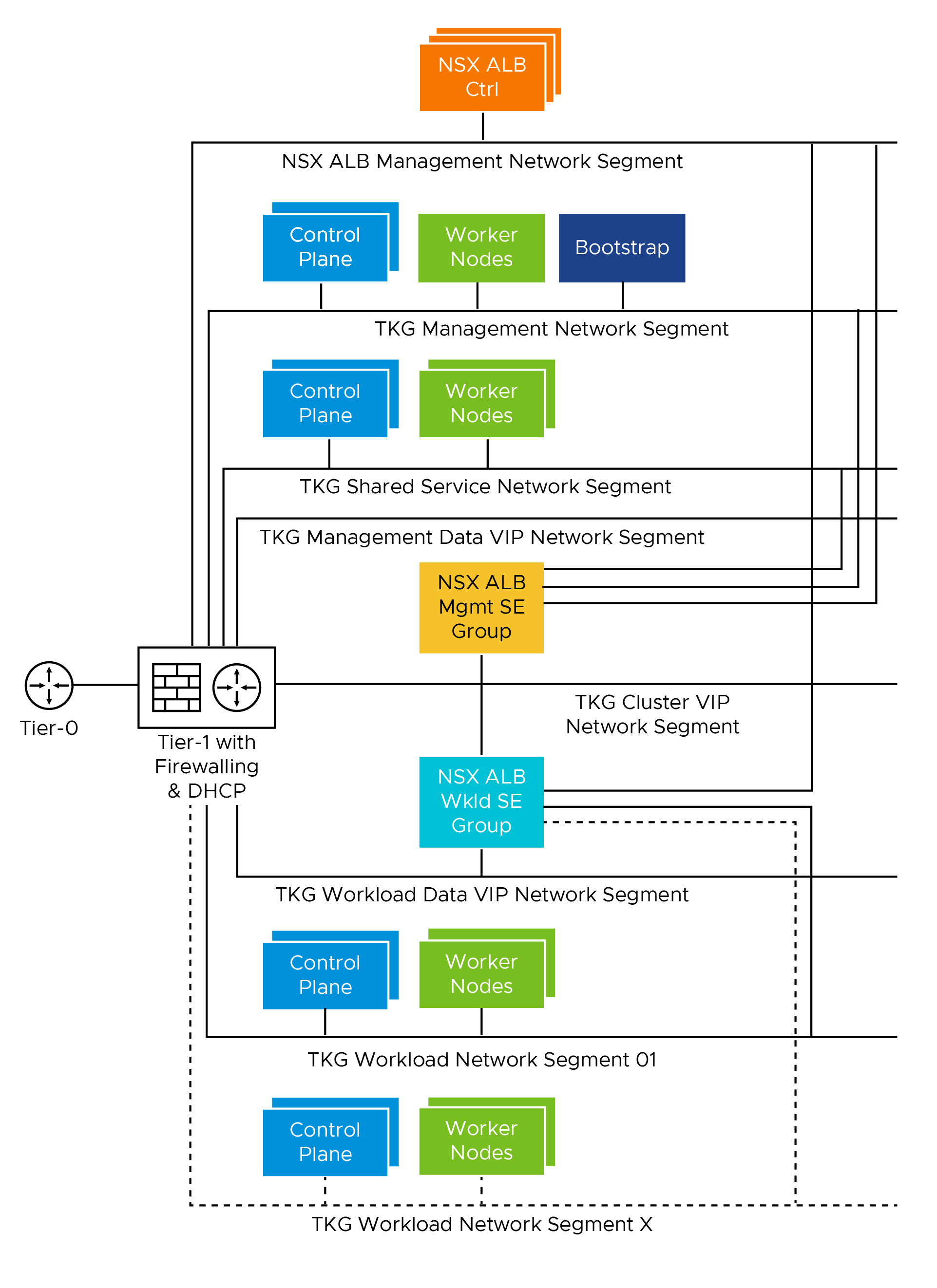
This topology provides the following benefits:
- Isolates and separates SDDC management components (vCenter, ESX) from the Tanzu Kubernetes Grid components. This reference design allows only minimum connectivity between the Tanzu Kubernetes Grid clusters and NSX Advanced Load Balancer and the vCenter Server.
- Isolates and separates the NSX Advanced Load Balancer management network segment from the Tanzu Kubernetes Grid management segment and the Tanzu Kubernetes Grid workload segments.
- Depending on the workload cluster type and use case, multiple workload clusters can leverage the same logical segments or new segments can be used for each workload cluster. To isolate and separate Tanzu Kubernetes Grid workload cluster networking from each other, VMware recommends that you use separate logical segments for each workload cluster and configure the required firewall between these networks. See Firewall Recommendations for more details.
- Separates provider and tenant access to the Tanzu Kubernetes Grid environment.
- Only provider administrators need access to the Tanzu Kubernetes Grid management cluster. Allowing only administrators to access the Tanzu Kubernetes Grid management cluster prevents tenants from attempting to connect to the Tanzu Kubernetes Grid management cluster.
Network Requirements
As per the defined architecture, the list of required networks includes:
| Network Type | DHCP Service | Description & Recommendations |
|---|---|---|
| NSX ALB management network | Optional | NSX ALB controllers and SEs are attached to this network.
|
| TKG management network | Yes | Control plane and worker nodes of TKG management cluster clusters are attached to this network. |
| TKG shared services network | Yes | Control plane and worker nodes of TKG shared services cluster are attached to this network. |
| TKG workload network | Yes | Control plane and worker nodes of TKG workload clusters are attached to this network. |
| TKG cluster VIP/data network | Optional | Virtual services for Control plane HA of all TKG clusters (management, shared services, and workload). |
| TKG management VIP/data network | Optional | Virtual services for all user-managed packages (such as Contour and Harbor) hosted on the shared services cluster. |
| TKG workload VIP/data network | Optional | Virtual services for all applications hosted on the workload clusters. |
Network Recommendations
The key network recommendations for a production-grade Tanzu Kubernetes Grid deployment with NSX-T Data Center Networking are as follows:
| Decision ID | Design Decision | Design Justification | Design Implications |
|---|---|---|---|
| TKO-NET-001 | Use separate networks for TKG management and workload clusters. | To have a flexible firewall and security policies. | Sharing the same network for multiple clusters can complicate the creation of firewall rules. |
| TKO-NET-002 | Use separate networks for workload clusters based on their usage. | Isolate production Kubernetes clusters from dev/test clusters. | A separate set of service engines can be used to separate dev/test workload clusters from prod clusters. |
| TKO-NET-003 | Configure DHCP for TKG clusters. | Tanzu Kubernetes Grid does not support static IP assignments for Kubernetes VM components. | Enable DHCP on the logical segments that are used to host TKG clusters. |
Subnet and CIDR Examples
The deployment described in this document makes use of the following CIDR.
| Network Type | Port Group Name | Gateway CIDR | DHCP Pool | NSX ALB IP Pool |
|---|---|---|---|---|
| NSX ALB management network | sfo01-w01-vds01-albmanagement |
192.168.11.1/27 | 192.168.11.15 - 192.168.11.30 | NA |
| TKG management network | sfo01-w01-vds01-tkgmanagement |
192.168.12.1/24 | 192.168.12.2 - 192.168.12.251 | NA |
| TKG workload network | sfo01-w01-vds01-tkgworkload |
192.168.13.1/24 | 192.168.13.2 - 192.168.13.251 | NA |
| TKG cluster VIP network | sfo01-w01-vds01-tkgclustervip |
192.168.14.1/26 | 192.168.14.2 - 192.168.14.30 | 192.168.14.31 - 192.168.14.60 |
| TKG Management VIP Network | sfo01-w01-vds01-tkgmanagementvip |
192.168.15.1/26 | 192.168.15.2 - 192.168.15.30 | 192.168.15.31 - 192.168.15.60 |
| TKG workload VIP network | sfo01-w01-vds01-tkgworkloadvip |
192.168.16.1/26 | 192.168.16.2 - 192.168.16.30 | 192.168.16.31 - 192.168.16.60 |
| TKG shared services network | sfo01-w01-vds01-tkgshared |
192.168.17.1/24 | 192.168.17.2 - 192.168.17.251 | NA |
Firewall Requirements
To prepare the firewall, you must collet the following information:
- NSX Advanced Load Balancer controller nodes and Cluster IP address
- NSX Advanced Load Balancer management network CIDR
- Tanzu Kubernetes Grid management network CIDR
- Tanzu Kubernetes Grid shared services network CIDR
- Tanzu Kubernetes Grid workload network CIDR
- Tanzu Kubernetes Grid cluster VIP address range
- Tanzu Kubernetes Grid Management VIP address range
- Tanzu Kubernetes Grid Workload VIP address range
- Client machine IP address
- Bootstrap machine IP address
- Harbor registry IP address
- vCenter Server IP address
- DNS server IP address(es)
- NTP server(s)
VMware Cloud on AWS uses a management gateway and compute gateway. These gateways need firewall rules to allow traffic for Tanzu Kubernetes Grid deployments.
The following table provides a list of firewall rules based on the assumption that there is no firewall within a subnet/VLAN.
| Source | Destination | Protocol:Port | Description |
|---|---|---|---|
| Client machine | NSX ALB controller nodes and cluster IP address. | TCP:443 | To access NSX ALB portal for configuration. |
| Client machine | vCenter Server | TCP:443 | To create resource pools, VM folders, etc, in vCenter. |
Bootstrap machine |
projects.registry.vmware.com | TCP:443 | To pull binaries from VMware public repo for TKG installation. |
Bootstrap machine |
TKG VIP network (cluster endpoint) | TCP:6443 | Allows bootstrap machine to communicate with cluster. |
TKG management network CIDR TKG shared services network CIDR. TKG workload network CIDR. |
DNS Server
|
UDP:53
|
DNS service
|
TKG management network CIDR TKG shared services network CIDR. TKG workload network CIDR. |
vCenter IP | TCP:443 | Allows components to access vCenter to create VMs and storage volumes. |
TKG management network CIDR. TKG shared services network CIDR. TKG workload network CIDR. |
TKG cluster VIP Range. | TCP:6443 | For management cluster to configure shared services and workload clusters. |
TKG management network TKG shared services network TKG workload networks |
Internet | TCP:443 | For interaction with Tanzu Mission Control, Tanzu Observability, and Tanzu Service Mesh. |
TKG management network TKG shared services network TKG workload networks |
NSX ALB controllers and cluster IP address. | TCP:443 | Allow Avi Kubernetes Operator (AKO) and AKO Operator (AKOO) access to NSX ALB controller. |
| NSX ALB controllers. | vCenter and ESXi Hosts | TCP:443 | Allow NSX ALB to discover vCenter objects and deploy SEs as required. |
| NSX ALB management network CIDR. | DNS server NTP server |
UDP:53 UDP:123 |
DNS service Time synchronization |
Optional Firewall Rules
| Source | Destination | Protocol:Port | Description |
|---|---|---|---|
| TKG management network CIDR TKG shared services network CIDR. TKG workload network CIDR. |
Harbor registry (optional) |
TCP:443 | Allows components to retrieve container images from a local image registry. |
Client machine |
console.cloud.vmware.com *.tmc.cloud.vmware.com projects.registry.vmware.com |
TCP:443 | To access cloud Services portal to configure networks in VMC SDDC. To access the TMC portal for TKG clusters registration and other SaaS integration. To pull binaries from VMware public repo for TKG installation. |
| Client machine | TKG management VIP range. TKG Workload VIP range. |
TCP:80 TCP:443 |
To http/https workloads in shared services and workload cluster. |
NSX Advanced Load Balancer Recommendations
The following table provides the recommendations for configuring NSX Advanced Load Balancer in a vSphere with Tanzu environment.
| Decision ID | Design Decision | Design Justification | Design Implications |
|---|---|---|---|
| TKO-ALB-001 | Deploy NSX ALB controller cluster nodes on a network dedicated to NSX-ALB. | Isolate NSX ALB traffic from infrastructure management traffic and Kubernetes workloads. | Additional Network (VLAN ) is required. |
| TKO-ALB-002 | Deploy 3 NSX ALB controllers nodes. | To achieve high availability for the NSX ALB platform. In clustered mode, NSX ALB availability is not impacted by an individual controller node failure. The failed node can be removed from the cluster and redeployed if recovery is not possible. Provides the highest level of uptime for a site. | Additional resource requirements. |
| TKO-ALB-003 | Under Compute policies create ‘VM-VM anti-affinity’ rule that prevents collocation of the NSX ALB Controllers VMs on the same host. | vSphere places NSX Advanced Load Balancer Controller VMs in a way that always ensures maximum HA. | Affinity Rules needs to be configured manually. |
| TKO-ALB-004 | Add vCenter as No Orchestrator type. | VMConAWS NSX-T have only limited Access. CloudAdmin user have Limited Access. |
Service Engines need to be deployed manually. VIP networks and Server Networks need to be assigned manually. Service engine group need to be assigned manually. |
| TKO-ALB-005 | Use static IP addresses for the NSX ALB controllers. | NSX ALB Controller cluster uses management IP addresses to form and maintain quorum for the control plane cluster. Any changes to management IP addresses will be disruptive. | None |
| TKO-ALB-006 | Reserve an IP address in the NSX ALB management subnet to be used as the cluster IP address for the controller cluster. | NSX ALB portal is always accessible over cluster IP address regardless of a specific individual controller node failure. | Additional IP is required. |
| TKO-ALB-007 | Create a dedicated resource pool with appropriate reservations for NSX ALB controllers. | Guarantees the CPU and Memory allocation for NSX ALB Controllers and avoids performance degradation in case of resource contention. | None |
| TKO-ALB-008 | Replace default NSX ALB certificates with Custom CA or Public CA-signed certificates that contains SAN entries of all Controller nodes. | To establish a trusted connection with other infra components, and the default certificate does not include SAN entries which is not acceptable by Tanzu. | None, SAN entries are not applicable if wild card certificate is used. |
| TKO-ALB-009 | Configure NSX ALB backup with a remote server as backup location. | Periodic backup of NSX ALB configuration database is recommended. The database defines all clouds, all virtual services, all users, and others. As a best practice, store backups in an external location to provide backup capabilities in case of entire cluster failure. | Additional Operational Overhead. Additional infrastructure Resource. |
| TKO-ALB-010 | Configure Remote logging for NSX ALB Controller to send events on Syslog. | For operations teams to be able to centrally monitor NSX ALB and escalate alerts, events must be sent from the NSX ALB Controller. | Additional Operational Overhead. Additional infrastructure Resource |
| TKO-ALB-011 | Use LDAP/SAML based Authentication for NSX ALB. | Helps to Maintain Role based Access Control. | Additional Configuration is required. |
NSX Advanced Load Balancer Service Engine Recommendations
| Decision ID | Design Decision | Design Justification | Design Implications |
|---|---|---|---|
| TKO-ALB-SE-001 | NSX ALB Service Engine High Availability set to Active/Active. | Provides higher resiliency, optimum performance, and utilization compared to N+M and/or Active/Standby. | Requires Enterprise Licensing. Certain applications might not work in Active/ Active mode. For instance, applications that require preserving client IP use the Legacy Active/ Standby HA mode. |
| TKO-ALB-SE-002 | Dedicated Service Engine Group for the TKG Management. | SE resources are guaranteed for TKG Management Stack and provides data path segregation for Management and Tenant Application. | Dedicated service engine Groups increase licensing cost. |
| TKO-ALB-SE-003 | Dedicated Service Engine Group for the TKG Workload Clusters Depending on the nature and type of workloads (dev/prod/test). | SE resources are guaranteed for single or set of workload clusters and provides data path segregation for Tenant Application hosted on workload clusters. | Dedicated service engine Groups increase licensing cost. |
| TKO-ALB-SE-004 | Enable ALB Service Engine Self Elections. | Enable SEs to elect a primary amongst themselves in the absence of connectivity to the NSX ALB controller. | None |
| TKO-ALB-SE-005 | Set ‘Placement across the Service Engines’ setting to ‘Compact’. | This allows maximum utilization of capacity. | None |
| TKO-ALB-SE-006 | Under Compute policies Create a ‘VM-VM anti-affinity rule for SE engines part of the same SE group that prevents collocation of the Service Engine VMs on the same host. | vSphere will take care of placing the Service Engine VMs in a way that always ensures maximum HA for the Service Engines part of a Service Engine group. | Affinity Rules needs to be configured manually. |
| TKO-ALB-SE-007 | Reserve Memory and CPU for Service Engines. | The Service Engines are a critical infrastructure component providing load-balancing services to mission-critical applications. Guarantees the CPU and Memory allocation for SE VM and avoids performance degradation in case of resource contention. | You must perform additional configuration to set up the reservations. |
Kubernetes Ingress Routing
The default installation of Tanzu Kubernetes Grid does not install an ingress controller. Users can install Contour (available for installation through Tanzu Packages) or any third-party ingress controller of their choice.
Contour is an open-source controller for Kubernetes Ingress routing. Contour can be installed in the shared services cluster on any Tanzu Kubernetes Cluster. Deploying Contour is a prerequisite if you want to deploy the Prometheus, Grafana, and Harbor Packages on a workload cluster.
For more information about Contour, see Contour site and Implementing Ingress Control with Contour.
Another option for ingress control is to use the NSX Advanced Load Balancer Kubernetes ingress controller which offers an advanced L7 ingress for containerized applications that are deployed in the Tanzu Kubernetes workload cluster.

For more information about the NSX Advanced Load Balancer ingress controller, see Configuring L7 Ingress with NSX Advanced Load Balancer.
Tanzu Service Mesh, a SaaS offering for modern applications running across multi-cluster, multi-clouds, also offers an ingress controller based on Istio.
Each ingress controller has its own pros and cons. The following table provides general recommendations for choosing an ingress controller for your Kubernetes environment.
| Ingress Controller | Use Cases |
|---|---|
| Contour | Use contour when only north-south traffic is needed in a Kubernetes cluster. You can apply security policies for north-south traffic by defining the policies in the applications manifest file. It’s a reliable solution for simple Kubernetes workloads. |
| Istio | Use Istio ingress controller when you intend to provide security, traffic direction, and insight within the cluster (east-west traffic) and between the cluster and the outside world (north-south traffic). |
| NSX ALB Ingress controller | Use NSX ALB ingress controller when a containerized application requires features like local and global server load balancing (GSLB), web application firewall (WAF), performance monitoring, and so on. |
NSX Advanced Load Balancer as in L4+L7 Ingress Service Provider
As a load balancer, NSX Advanced Load Balancer provides an L4+L7 load balancing solution for vSphere. It includes a Kubernetes operator that integrates with the Kubernetes API to manage the lifecycle of load balancing and ingress resources for workloads.
Legacy ingress services for Kubernetes include multiple disparate solutions. The services and products contain independent components that are difficult to manage and troubleshoot. The ingress services have reduced observability capabilities with little analytics, and they lack comprehensive visibility into the applications that run on the system. Cloud-native automation is difficult in the legacy ingress services.
In comparison to the legacy Kubernetes ingress services, NSX Advanced Load Balancer has comprehensive load balancing and ingress services features. As a single solution with a central control, NSX Advanced Load Balancer is easy to manage and troubleshoot. NSX Advanced Load Balancer supports real-time telemetry with an insight into the applications that run on the system. The elastic auto-scaling and the decision automation features highlight the cloud-native automation capabilities of NSX Advanced Load Balancer.
NSX Advanced Load Balancer also lets you configure L7 ingress for your workload clusters by using one of the following options:
- L7 ingress in ClusterIP mode
- L7 ingress in NodePortLocal mode
- L7 ingress in NodePort mode
- NSX Advanced Load Balancer L4 ingress with Contour L7 ingress
L7 Ingress in ClusterIP Mode
This option enables NSX Advanced Load Balancer L7 ingress capabilities, including sending traffic directly from the service engines (SEs) to the pods, preventing multiple hops that other ingress solutions need when sending packets from the load balancer to the right node where the pod runs. The NSX Advanced Load Balancer controller creates a virtual service with a backend pool with the pod IP addresses which helps to send the traffic directly to the pods.
However, each workload cluster needs a dedicated SE group for Avi Kubernetes Operator (AKO) to work, which could increase the number of SEs you need for your environment. This mode is used when you have a small number of workload clusters.
L7 Ingress in NodePort Mode
The NodePort mode is the default mode when AKO is installed on Tanzu Kubernetes Grid. This option allows your workload clusters to share SE groups and it is fully supported by VMware. With this option, the services of your workloads must be set to NodePort instead of ClusterIP even when accompanied by an ingress object. This ensures that NodePorts are created on the worker nodes and traffic can flow through the SEs to the pods via the NodePorts. Kube-Proxy, which runs on each node as DaemonSet, creates network rules to expose the application endpoints to each of the nodes in the format “NodeIP:NodePort”. The NodePort value is the same for a service on all the nodes. It exposes the port on all the nodes of the Kubernetes Cluster, even if the pods are not running on it.
L7 Ingress in NodePortLocal Mode
This feature is supported only with Antrea CNI. The primary difference between this mode and the NodePort mode is that the traffic is sent directly to the pods in your workload cluster through node ports without interfering Kube-proxy. With this option, the workload clusters can share SE groups. Similar to the ClusterIP Mode, this option avoids the potential extra hop when sending traffic from the NSX Advanced Load Balancer SEs to the pod by targeting the right nodes where the pods run.
Antrea agent configures NodePortLocal port mapping rules at the node in the format “NodeIP:Unique Port” to expose each pod on the node on which the pod of the service is running. The default range of the port number is 61000-62000. Even if the pods of the service are running on the same Kubernetes node, Antrea agent publishes unique ports to expose the pods at the node level to integrate with the load balancer.
NSX Advanced Load Balancer L4 Ingress with Contour L7 Ingress
This option does not have all the NSX Advanced Load Balancer L7 ingress capabilities but uses it for L4 load balancing only and leverages Contour for L7 Ingress. This also allows sharing SE groups across workload clusters. This option is supported by VMware and it requires minimal setup.
NSX Advanced Load Balancer L7 Ingress Recommendations
| Decision ID | Design Decision | Design Justification | Design Implications |
|---|---|---|---|
| TKO-ALB-L7-001 | Deploy NSX ALB L7 ingress in NodePortLocal mode. | - Gives good Network hop efficiency. - Helps to reduce the east-west traffic and encapsulation overhead. - Service Engine groups are shared across clusters and the load-balancing persistence is also supported. |
Supported only with Antrea CNI with IPV4 addressing. |
Container Registry
VMware Tanzu for Kubernetes Operations using Tanzu Kubernetes Grid includes Harbor as a container registry. Harbor provides a location for pushing, pulling, storing, and scanning container images used in your Kubernetes clusters.
Harbor registry is used for day-2 operations of the Tanzu Kubernetes workload clusters. Typical day-2 operations include tasks such as pulling images from Harbor for application deployment, pushing custom images to Harbor, etc.
You may use one of the following methods to install Harbor:
-
Tanzu Kubernetes Grid Package deployment - VMware recommends this installation method for general use cases. The Tanzu packages, including Harbor, must either be pulled directly from VMware or be hosted in an internal registry.
-
VM-based deployment using OVA - VMware recommends this installation method in cases where Tanzu Kubernetes Grid is being installed in an air-gapped or Internet-restricted environment, and no pre-existing image registry exists to host the Tanzu Kubernetes Grid system images. VM-based deployments are only supported by VMware Global Support Services to host the system images for air-gapped or Internet-restricted deployments. Do not use this method for hosting application images.
If you are deploying Harbor without a publicly signed certificate, you must include the Harbor root CA in your Tanzu Kubernetes Grid clusters. To do so, follow the procedure in Trust Custom CA Certificates on Cluster Nodes.

Tanzu Kubernetes Grid Monitoring
Monitoring for the Tanzu Kubernetes clusters is provided through Prometheus and Grafana. Both Prometheus and Grafana can be installed on Tanzu Kubernetes Grid clusters using Tanzu Packages.
Prometheus is an open-source system monitoring and alerting toolkit. It can collect metrics from target clusters at specified intervals, evaluate rule expressions, display the results, and trigger alerts if certain conditions arise. The Tanzu Kubernetes Grid implementation of Prometheus includes Alert Manager, which you can configure to notify you when certain events occur.
Grafana is an open-source visualization and analytics software. It allows you to query, visualize, alert on, and explore your metrics no matter where they are stored. Both Prometheus and Grafana are installed through user-managed Tanzu packages by creating the deployment manifests and invoking the tanzu package install command to deploy the packages in the Tanzu Kubernetes clusters.
The following diagram shows how the monitoring components on a cluster interact.
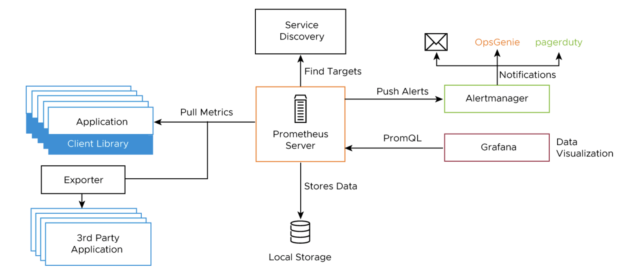
You can use out-of-the-box Kubernetes dashboards or you can create new dashboards to monitor compute, network, and storage utilization of Kubernetes objects such as Clusters, Namespaces, Pods, etc.
You can also monitor your Tanzu Kubernetes Grid clusters using Tanzu Observability which is a SaaS offering by VMware. Tanzu Observability provides various out-of-the-box dashboards. You can customize the dashboards for your particular deployment. For information on how to customize Tanzu Observability dashboards for Tanzu for Kubernetes Operations, see Customize Tanzu Observability Dashboard for Tanzu for Kubernetes Operations.
Tanzu Kubernetes Grid Logging
Metrics and logs are critical for any system or application as they provide insights into the activities of the system or the application. It is important to have a central place to observe a multitude of metrics and log sources from multiple endpoints.
Log processing and forwarding in Tanzu Kubernetes Grid is provided via Fluent Bit. Fluent bit binaries are available as part of extensions and can be installed on management cluster or in workload cluster. Fluent Bit is a light-weight log processor and forwarder that allows you to collect data and logs from different sources, unify them, and send them to multiple destinations. VMware Tanzu Kubernetes Grid includes signed binaries for Fluent Bit that you can deploy on management clusters and on Tanzu Kubernetes clusters to provide a log-forwarding service.
Fluent Bit makes use of the Input Plug-ins, the filters, and the Output Plug-ins. The Input Plug-ins define the source from where it can collect data, and the output plug-ins define the destination where it should send the information. The Kubernetes filter will enrich the logs with Kubernetes metadata, specifically labels and annotations. Once you configure Input and Output plug-ins on the Tanzu Kubernetes Grid cluster. Fluent Bit is installed as a user-managed package.
Fluent Bit integrates with logging platforms such as VMware Aria Operations for Logs, Elasticsearch, Kafka, Splunk, or an HTTP endpoint. For more details about configuring Fluent Bit to your logging provider, see Implement Log Forwarding with Fluent Bit.
Bring Your Own Images for Tanzu Kubernetes Grid Deployment
You can build custom machine images for Tanzu Kubernetes Grid to use as a VM template for the management and Tanzu Kubernetes (workload) cluster nodes that it creates. Each custom machine image packages a base operating system (OS) version and a Kubernetes version, along with any additional customizations, into an image that runs on vSphere, Microsoft Azure infrastructure, and AWS (EC2) environments.
A custom image must be based on the operating system (OS) versions that are supported by Tanzu Kubernetes Grid. The table below provides a list of the operating systems that are supported for building custom images for Tanzu Kubernetes Grid.
| vSphere | AWS | Azure |
|---|---|---|
- Ubuntu 20.04 - Ubuntu 18.04 - RHEL 7 - Photon OS 3 - Windows 2019 |
- Ubuntu 20.04 - Ubuntu 18.04 - Amazon Linux 2 |
- Ubuntu 20.04 - Ubuntu 18.04 |
For additional information on building custom images for Tanzu Kubernetes Grid, see Build Machine Images.
Compliance and Security
VMware published Tanzu Kubernetes releases (TKrs), along with compatible versions of Kubernetes and supporting components, use the latest stable and generally-available update of the OS version that it packages, containing all current CVE and USN fixes, as of the day that the image is built. The image files are signed by VMware and have file names that contain a unique hash identifier.
VMware provides FIPS-capable Kubernetes OVA that can be used to deploy FIPS compliant Tanzu Kubernetes Grid management and workload clusters. Tanzu Kubernetes Grid core components, such as Kubelet, Kube-apiserver, Kube-controller manager, Kube-proxy, Kube-scheduler, Kubectl, Etcd, Coredns, Containerd, and Cri-tool are made FIPS compliant by compiling them with the BoringCrypto FIPS modules, an open-source cryptographic library that provides FIPS 140-2 approved algorithms.
Installation Experience
Tanzu Kubernetes Grid management cluster is the first component that you deploy to get started with Tanzu Kubernetes Grid.
You can deploy the management cluster in one of the following ways:
- Run the Tanzu Kubernetes Grid installer, a wizard interface that guides you through the process of deploying a management cluster. VMware recommends this method if you are installing a Tanzu Kubernetes Grid Management cluster for the first time.
- Create and edit YAML configuration files to use with CLI commands to deploy the management cluster.
By using the current version of the The Tanzu Kubernetes Grid Installation user interface, you can install Tanzu Kubernetes Grid on VMware vSphere, AWS, and Microsoft Azure. The UI provides a guided experience tailored to the IaaS, in this case on VMware vSphere backed by NSX-T Data Center networking.
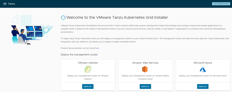
The installation of Tanzu Kubernetes Grid on VMware Cloud on AWS is done through the same UI as mentioned above but tailored to a vSphere environment.
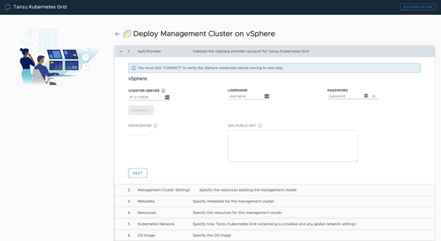
This installation process takes you through setting up TKG Management Cluster on your vSphere environment. Once the management cluster is deployed, you can register the management cluster with Tanzu Mission Control and deploy Tanzu Kubernetes shared services and workload clusters directly from the Tanzu Mission Control UI or Tanzu CLI to deploy Tanzu Kubernetes shared service and workload clusters.
Deployment Instructions
For instructions on how to deploy this reference design, see Deploy Tanzu for Kubernetes Operations in VMware Cloud on AWS.
Summary
Tanzu on VMware Cloud on AWS offers high-performance potential, convenience, and addresses the challenges of creating, testing, and updating Kubernetes platforms in a consolidated production environment. This validated approach results in a production quality installation with all the application services needed to serve combined or uniquely separated workload types through a combined infrastructure solution.
This plan meets many day-0 needs for aligning product capabilities, such as configuring firewall rules, networking, load balancing, and workload compute, to the full stack infrastructure.
Supplemental Information
Automating Deployment of Service Engines
As discussed, Avi Vantage is installed in No Orchestrator mode on VMWare Cloud on AWS. Therefore, the deployment of service engines (SE) on VMware Cloud on AWS is not orchestrated by the Avi Controller. Once SE is integrated with the Avi Controller, virtual service placement and scaling can be handled centrally from the Avi Controller. A pair of service engines provide HA for load balancing.
It is troublesome to manually deploy a pair of service engines for each tenant using the Import OVA workflow in VMware Cloud on AWS. Therefore, we recommend using GOVC in conjunction with Python to obtain the OVF properties as a JSON file and then customizing the JSON file for each service engine.
The following example JSON file can be used to automate the provisioning of service engines ready for use with Tanzu Kubernetes Grid.
{
  "DiskProvisioning": "flat",
  "IPAllocationPolicy": "fixedPolicy",
  "IPProtocol": "IPv4",
  "PropertyMapping": [
    {
      "Key": "AVICNTRL",
      "Value": "<ip-address-of-avi-controller>"
    },

    {
      "Key": "AVISETYPE",
      "Value": "NETWORK_ADMIN"
    },
    {
      "Key": "AVICNTRL_AUTHTOKEN",
      "Value": "<avi-controller-auth-token>"
    },
    {
      "Key": "AVICNTRL_CLUSTERUUID",
      "Value": "<avi-controller-cluster-id>"
    },
    {
      "Key": "avi.mgmt-ip.SE",
      "Value": "<management-ip-address-of-service-engine>"
    },
    {
      "Key": "avi.mgmt-mask.SE",
      "Value": "255.255.255.0"
    },
    {
      "Key": "avi.default-gw.SE",
      "Value": "<avi-management-network-gateway>"
    },
    {
      "Key": "avi.DNS.SE",
      "Value": "<dns-server>"
    },
    {
      "Key": "avi.sysadmin-public-key.SE",
      "Value": ""
    }
  ],
  "NetworkMapping": [
    {
      "Name": "Management",
      "Network": "avi-management"
    },
    {
      "Name": "Data Network 1",
      "Network": "<tkg-workload-1-cluster-network-segment-name>"
    },
    {
      "Name": "Data Network 2",
      "Network": "<tkg-workload-2-cluster-network-segment-name>"
    },
    {
      "Name": "Data Network 3",
      "Network": "<tkg-workload-3-cluster-network-segment-name>"
    },
    {
      "Name": "Data Network 4",
      "Network": "<tkg-workload-4-cluster-network-segment-name>"
    },
    {
      "Name": "Data Network 5",
      "Network": "<tkg-workload-5-cluster-network-segment-name>"
    },
    {
      "Name": "Data Network 6",
      "Network": "<tkg-workload-6-cluster-network-segment-name>"
    },
    {
      "Name": "Data Network 7",
      "Network": "<tkg-workload-7-cluster-network-segment-name>"
    },
    {
      "Name": "Data Network 8",
      "Network": "<tkg-workload-8-cluster-network-segment-name>"
    },
    {
      "Name": "Data Network 9",
      "Network": "<tkg-workload-9-cluster-network-segment-name>"
    }
  ],
  "MarkAsTemplate": false,
  "PowerOn": true,
  "InjectOvfEnv": false,
  "WaitForIP": false,
  "Name": "se-1"
}
Provision each service engine using the following code.
export GOVC_URL=<fqdn-of-vcenter-in-vmware-cloud-on-aws>
export [email protected]
export GOVC_PASSWORD=<[email protected]>
export GOVC_INSECURE=false
govc import.spec /home/admin/se.ova | python -m json.tool > se-1.json
govc import.ova -pool=*/Resources/Compute-ResourcePool/TKG/SEs -ds=WorkloadDatastore --options=/home/admin/se-1.json /home/admin/se.ova
This deploys a new service engine with a VM name of _se-1_ into the resource pool _Compute-ResourcePool/TKG/SEs_. Since the _PowerOn_ parameter is set to _true_, the service engine boots up automatically and since we have set the key value pairs for the following, the service engine is automatically registered with Avi Controller and is ready for further configuration in Avi Vantage:
"Key": "AVICNTRL",
"Value": "<ip-address-of-avi-controller>"
"Key": "AVICNTRL_CLUSTERUUID",
"Value": "<avi-controller-cluster-id>"
"Key": "avi.mgmt-ip.SE",
"Value": "<management-ip-address-of-service-engine>"
Appendix A - Configure Node Sizes
The Tanzu CLI creates the individual nodes of management clusters and Tanzu Kubernetes clusters according to the settings that you provide in the configuration file.
On vSphere, you can configure all node VMs to have the same predefined configurations, set different predefined configurations for control plane and worker nodes, or customize the configurations of the nodes. By using these settings, you can create clusters that have nodes with different configurations to the management cluster nodes. You can also create clusters in which the control plane nodes and worker nodes have different configurations.
Use Predefined Node Configurations
The Tanzu CLI provides the following predefined configurations for cluster nodes:
| Size | CPU | Memory (in GB) | Disk (in GB) |
|---|---|---|---|
| Small | 2 | 4 | 20 |
| Medium | 2 | 8 | 40 |
| Large | 4 | 16 | 40 |
| Extra-large | 8 | 32 | 80 |
To create a cluster in which all of the control plane and worker node VMs are the same size, specify the SIZE variable. If you set the SIZE variable, all nodes will be created with the configuration that you set.
SIZE: "large"
To create a cluster in which the control plane and worker node VMs are different sizes, specify the CONTROLPLANE_SIZE and WORKER_SIZE options.
CONTROLPLANE_SIZE: "medium"WORKER_SIZE: "large"
You can combine the CONTROLPLANE_SIZE and WORKER_SIZE options with the SIZE option. For example, if you specify SIZE: "large" with WORKER_SIZE: "extra-large", the control plane nodes will be set to large and worker nodes will be set to extra-large.
SIZE: "large"WORKER_SIZE: "extra-large"
Define Custom Node Configurations
You can customize the configuration of the nodes rather than using the predefined configurations.
To use the same custom configuration for all nodes, specify the VSPHERE_NUM_CPUS, VSPHERE_DISK_GIB, and VSPHERE_MEM_MIB options.
VSPHERE_NUM_CPUS: 2VSPHERE_DISK_GIB: 40VSPHERE_MEM_MIB: 4096
To define different custom configurations for control plane nodes and worker nodes, specify the VSPHERE_CONTROL_PLANE_* and VSPHERE_WORKER_*
VSPHERE_CONTROL_PLANE_NUM_CPUS: 2VSPHERE_CONTROL_PLANE_DISK_GIB: 20VSPHERE_CONTROL_PLANE_MEM_MIB: 8192VSPHERE_WORKER_NUM_CPUS: 4VSPHERE_WORKER_DISK_GIB: 40VSPHERE_WORKER_MEM_MIB: 4096
Appendix B - NSX Advanced Load Balancer Sizing Guidelines
NSX Advanced Load Balancer Controller Sizing Guidelines
Controllers are classified into the following categories:
| Classification | vCPUs | Memory (GB) | Virtual Services | Avi SE Scale |
|---|---|---|---|---|
| Essentials | 4 | 12 | 0-50 | 0-10 |
| Small | 8 | 24 | 0-200 | 0-100 |
| Medium | 16 | 32 | 200-1000 | 100-200 |
| Large | 24 | 48 | 1000-5000 | 200-400 |
The number of virtual services that can be deployed per controller cluster is directly proportional to the controller cluster size. For more information, see the NSX Advanced Load Balancer Configuration Maximums Guide.
Service Engine Sizing Guidelines
The service engines can be configured with a minimum of 1 vCPU core and 2 GB RAM up to a maximum of 64 vCPU cores and 256 GB RAM. The following table provides guidance for sizing a service engine VM with regards to performance:
| Performance metric | Per core performance | Maximum performance on a single Service Engine VM |
|---|---|---|
| HTTP Throughput | 5 Gbps | 7 Gbps |
| HTTP requests per second | 50k | 175k |
| SSL Throughput | 1 Gbps | 7 Gbps |
| SSL TPS (RSA2K) | 750 | 40K |
| SSL TPS (ECC) | 2000 | 40K |
Multiple performance vectors or features may have an impact on performance. For instance, to achieve 1 Gb/s of SSL throughput and 2000 TPS of SSL with EC certificates, NSX Advanced Load Balancer recommends two cores.
