


The adapter configuration process on the ESXi host involves setting up VMkernel binding for an RDMA network adapter, and then adding a software NVMe over RDMA adapter. You can then add an NVMe controller.
| Action | Description |
|---|---|
| View RDMA Network Adapters | On your ESXi host, install a network adapter that supports RDMA (RoCE v2). For example, Mellanox Technologies MT27700 Family ConnectX-4. After you install the network adapter, use the vSphere Client to review the RDMA adapter and a physical network adapter. |
| Configure VMkernel Binding for the RDMA Adapter | Port binding for NVMe over RDMA involves creating a switch and connecting the physical network adapter and the VMkernel adapter to the switch. Through this connection, the RDMA adapter becomes bound to the VMkernel adapter. In the configuration, you can use a vSphere standard switch or a vSphere distributed switch. |
| Add the Software NVMe over RDMA Adapter | Use the vSphere Client to activate the software storage adapters for NVMe over RDMA. |
| Add Controllers for NVMe over Fabrics | Use the vSphere Client to add an NVMe controller. After you add the controller, the NVMe namespaces associated with the controller become available to your ESXi host. The NVMe storage devices that represent the namespaces in the ESXi environment appear on the storage devices list. |
The following video walks you through the steps of configuring NVMe over RDMA adapters.
View RDMA Network Adapters
After you install a network adapter that supports RDMA (RoCE v2) on your ESXi host, use the vSphere Client to review the RDMA adapter and a physical network adapter.
Procedure
- In the vSphere Client, verify that the RDMA adapter is discovered by your host.
- Navigate to the host.
- Click the Configure tab.
- Under Networking, click RDMA adapters.
In this example, the RDMA adapter appears on the list as vmrdma0. The Paired Uplink column displays the network component as the vmnic1 physical network adapter.

- To verify the description of the adapter, select the RDMA adapter from the list, and click the Properties tab.
Configure VMkernel Binding for the RDMA Adapter
Port binding for NVMe over RDMA involves creating a switch and connecting the physical network adapter and the VMkernel adapter to the switch. Through this connection, the RDMA adapter becomes bound to the VMkernel adapter. In the configuration, you can use a vSphere standard switch or a vSphere distributed switch.
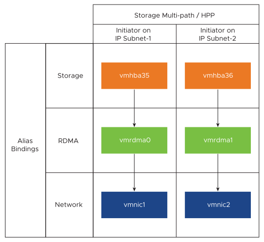
The following diagram displays the port binding for the NVMe over RDMA adapter.
For more information about creating switches, see Create a vSphere Standard Switch or Create a vSphere Distributed Switch in the vSphere Networking documentation.
Example of Network Topology with NVMe over RDMA
In this example, two vSphere standard switches and two uplinks (RDMA capable NICs) provide high availability. They connect to two controller pairs in two subnets.
HA with Multiple vSwitches and Multiple Uplinks (RNICs)

Configure VMkernel Binding with a vSphere Standard Switch
You can configure VMkernel port binding for the RDMA adapter using a vSphere standard switch and one uplink per switch. Configuring the network connection involves creating a virtual VMkernel adapter for each physical network adapter. You use 1:1 mapping between each virtual and physical network adapter.
Procedure
- Create a vSphere standard switch with a VMkernel adapter and the network component.
- In the vSphere Client, select your host and click the Networks tab.
- Click .
- Select VMkernel Network Adapter and click NEXT.
- Select New standard switch and click NEXT.
- Under Assigned adapters, click +.
The list of available physical adapters is displayed.
- Select the required physical adapter vmnic, and click OK.
Note: Ensure to select the physical network adapter that corresponds to the RDMA adapter. To see the association between the RDMA adapter vmrdma, and the physical network adapter vmnic, see View RDMA Network Adapters.
- Under VMkernel port settings, enter the required values.
If you are using VLAN for the storage path, enter the VLAN ID.
- In the IP settings list, enter the VMkernel IPv4 settings.
- Under Available services, select NVMe over RDMA.
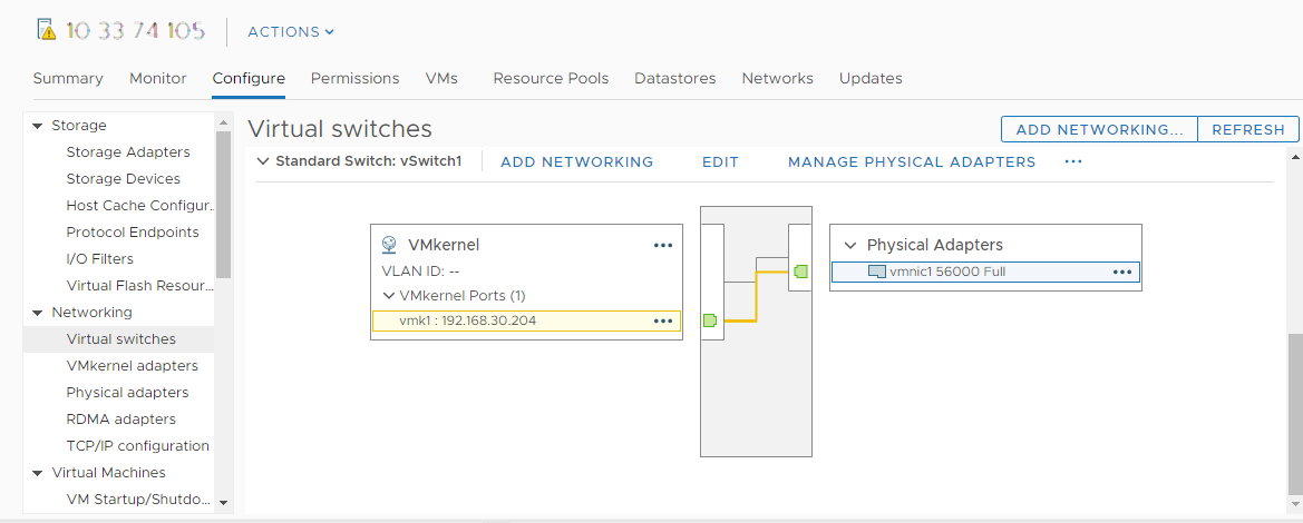
- Verify that your switch is correctly configured.
- On the Configure tab, select Virtual switches under Networking.
- Expand the switch and verify its configuration.
The illustration shows that the physical network adapter and the VMkernel adapter are connected to the vSphere standard switch. Through this connection, the RDMA adapter is bound to the VMkernel adapter.
- Verify the configuration of the VMkernel binding for the RDMA adapter.
- Under Networking list, click RDMA adapters, and select the RDMA adapter from the list.
- Click the VMkernel adapters binding tab and verify that the associated VMkernel adapter appears on the page.
In this example, the vmrdma0 RDMA adapter is paired to the vmnic1 network adapter and is connected to the vmk1 VMkernel adapter.

Configure VMkernel Binding with a vSphere Standard Switch and NIC Teaming
You can configure VMkernel port binding for the RDMA adapter using a vSphere standard switch with the NIC teaming configuration. You can use NIC teaming to achieve network redundancy. You can configure two or more network adapters (NICs) as a team for high availability and load balancing.
Procedure
Configure VMkernel Binding with a vSphere Distributed Switch
You can configure VMkernel port binding for the RDMA adapter using a vSphere distributed switch and one uplink per switch. Configuring the network connection involves creating a virtual VMkernel adapter for each physical network adapter. You use 1:1 mapping between each virtual and physical network adapter.
Procedure
- Create a vSphere distributed switch with a VMkernel adapter and the network component.
- In the vSphere Client, select Datacenter, and click the Networks tab.
- Click Actions , and select .
- Select a name for the switch.
Ensure that the location of the data center is present within your host, and click Next.
- Select a compatible ESXi version, and click Next.
- Enter the required number of uplinks, and click Finish.
- Add one or more hosts to your distributed virtual switch.
- In the vSphere Client, select Datacenter, and click Distributed Switches..
A list of available DSwitches appear.
- Right-click the DSwitch, and select Add and Manage Hosts from the menu.
- Select Add hosts, and click Next.
- Select your host, and click Next.
- Select Assign uplink.
- Enter the relevant uplink to assign the vmnic.
- Assign a VMkernel adapter, and click Next.
- In the vSphere Client, select the DSwitch, and click the Ports tab.
You can view the uplinks created for your switch here.
- In the vSphere Client, select Datacenter, and click Distributed Switches..
- Create distributed port groups for the NVMe over RDMA storage path.
- In the vSphere Client, select the required DSwitch.
- Click Actions and select .
- Under Configure Settings, enter the general properties of the port group.
If you have configured a specific VLAN, add it in the VLAN ID.Note: Network connectivity issues might occur if you do not configure VLAN properly.
- Configure the VMkernel adapters.
- In the vSphere Client, expand the DSwitch list, and select the distributed port group.
- Click .
- In the Select Member Hosts dialog box, select your host and click OK.
- In the Configure VMkernel Adapter dialog box, ensure that the MTU matches to the Switch MTU.
- Under Available services, select NVMe over RDMA for appropriate tagging.
- Click Finish.
- Repeat step b and step c to add multiple RDMA capable NICs.
- Set NIC teaming policies for the distributed port groups.
- In the Distributed Port Group, click .
- Click Teaming and Failover, and verify the active uplinks.
- Assign one uplink as Active for the port group, and the other uplink as Unused.
Repeat step c for each of the port groups created.
What to do next
Add Software NVMe over RDMA or NVMe over TCP Adapters
ESXi supports NVMe over RDMA and NVMe over TCP software adapters. Use the vSphere Client to add the software storage adapters for NVMe over RDMA or NVMe over TCP.
Prerequisites
- On your ESXi host, install an adapter that supports the following types of storage.
- NVMe over RDMA adapter. For example, Mellanox Technologies MT27700 Family ConnectX-4.
- NVMe over TCP adapter. For example, i40en.
- Configure the VMkernel binding for your adapters.
- For NVMe over RDMA, see Configure VMkernel Binding for the RDMA Adapter.
- For NVMe over TCP, see Configure VMkernel Binding for the NVMe over TCP Adapter.
Procedure
Results
Add Controllers for NVMe over Fabrics
Use the vSphere Client to add an NVMe controller. After you add the controller, the NVMe namespaces associated with the controller become available to your ESXi host. The NVMe storage devices that represent the namespaces in the ESXi environment appear on the storage devices list.
Prerequisites
- Make sure that your ESXi host has appropriate adapters for your type of storage. See Requirements for VMware NVMe Storage.
- If you use NVMe over RDMA (RoCE v2) storage, perform these tasks:
- If you use NVMe over TCP storage, perform these tasks:
Procedure
- In the vSphere Client, navigate to the ESXi host.
- Click the Configure tab.
- Under Storage, click Storage Adapters, and select the adapter (vmhba#) to configure.
- Click the Controllers tab, and click Add Controller.
- On the Add controller dialog box, select one of the following discovery methods.
Option Description Automatically This option indicates that your host can discover controllers automatically and accept connection to any available controller. - Specify the following parameters for to discover controllers.
- For NVMe over RDMA (RoCE v2), the IP address and transport port number.
- For NVMe over TCP, the IP address, transport port number, and the digest parameter.
- Click Discover Controllers.
- From the list of controllers, select the controller to use.
Manually With this method, you manually enter controller details. The host requests a connection to a specific controller using the parameters you specify: - Subsystem NQN
- Target port identification.
- For NVMe over RDMA (RoCE v2), the IP address and transport port number (optional).
- For NVMe over TCP, the IP address, transport port number (optional), and the digest parameter (optional).
- For NVMe over Fibre Channel, the WorldWideNodeName and WorldWidePortName.
- Admin queue size. An optional parameter that specifies the size of the admin queue of the controller. A default value is 16.
- Keepalive timeout. An optional parameter to specify in seconds the keep alive timeout between the adapter and the controller. A default timeout value is 60 seconds.
Note: IO Queue Size and IO Queue Number are optional parameters that can be set only through esxcli. - Specify the following parameters for to discover controllers.
Results
The controller appears on the list of controllers. Your host can now discover the NVMe namespaces that are associated with the controller. The NVMe storage devices that represent the namespaces in the ESXi environment appear on the storage devices list in the vSphere Client.
