The increase in flexibility that a software-defined system offers can result in increased levels of redundancy. Beginning with eliminating any single point of failure, station and process bus communications are interfaced with multiple servers staged as active-active or active-standby, and each physical and virtual device’s implementation must be carefully considered as system complexity is balanced with reliability.
When it comes to utility planning for n-1 failures (or beyond), the criticality of the associated service (generation or load) is weighed to determine what level of risk to adopt. This is often influenced by type of customers (medical, military), the interconnections that can be affected (transmission or generation feeding large areas), or specific regulatory requirements which must be upheld.
Redundancy in PTP
With physical devices, as shown in the reference architecture diagram (VVS Reference Architecture), redundancy must be implemented in PTP signals. There are a couple of ways to accomplish redundancy in PTP:
Duplicate PTP LAN hardware
With strategic WAN placement of PTP grandmasters in geographically disparate locations.
Both these methods can leverage PRP networking. The duplicating PTP LAN hardware method allows the network to survive a single clock or network failure and continue synchronization of all substation systems. However, distribution by local clocks only is more susceptible to GNSS spoofing or attack.
With strategic placement of PTP grandmasters, which leverages a wide area containing multiple grandmaster clocks, there is greater security in the design. Both the remote grandmasters and the local PTP signals can still be routed through PRP. But localized attacks or failures can easily be survived as the Best Master Clock Algorithm (BMCA) is leveraged to synchronize end devices to the next best master.

Testing the failover of a redundant PTP network is simple. Whether it is in the form of multiple masters or PRP, tests implemented must include forced failures. With two local master clocks, ensure that a forced failure of the ‘A’ device results in locking of any synchronized devices to ‘B’, and that the transition occurs quickly enough not to affect the performance of critical workloads.
Repeat this process with the failover from ‘B’ to ‘A’. And for a PTP WAN, the failure of a locked, synchronized grandmaster must have similar results, with a new lock being quickly established on the next best master. Any system failure must also generate an alarm for operations and on-call personnel to investigate.
Also verify that PTP networks are functioning over PRP by removing part of path ‘A’ to ensure a complete, healthy ‘B’ path satisfies traffic requirements for all end devices. This testing can be performed on any PRP routed traffic (typical for SV and GOOSE traffic).
Redundancy in I/O Translation
The merging units (to represent any I/O translation device) are also candidates for redundancy. In this case, the high voltage equipment being interfaced with is already installed for each utility standard requirements for maintaining availability. Merging Unit and HV Sensor Redundancy shows an example of redundancy in MUs and in the critical instrument transformers. The consolidation of digital signal output through IEC 61869-9 allows for more flexibility in MU application and therefore may also ease redundancy requirements. All MUs must participate in PRP networking.

Testing for failed MUs can be as simple as removing power to ensure the remaining ‘B’ (or ‘A’, in the case of backup failure) units can satisfy all required SV, GOOSE, or MMS signals. Ensure that PRP networks are tested. And some workloads can eventually incorporate additional intelligence for crosschecking signal validity. Testing an algorithm such as this can involve introducing errors (which is easy to delay using signal simulation) to evaluate the performance of end device detection and failover.
Redundancy in Physical and Virtual
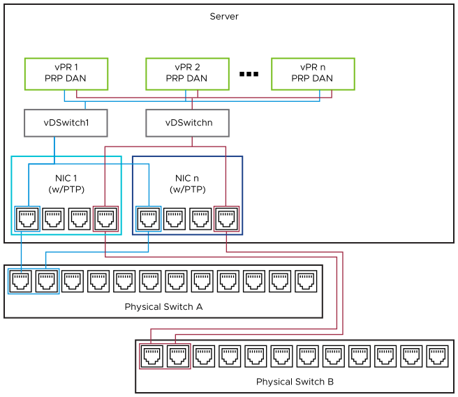
The redundancy of physical network switches and NICs is straightforward but has several configuration and component options. As seen in VVS Reference Architecture, the vPAC reference architecture includes a PRP network separated by duplicate switches.
If the process bus traffic requires segregation from station bus (for cyber security reasons), an additional set of switches can be incorporated (see Separate Process/Station Bus). The loss of any physical switch or cable does not result in any vPR failure. However, the failure of a NIC acting as a PRP DAN causes a PCI-passthrough-supported vPR to lose all process bus traffic.

Another architecture can leverage a VM’s PRP DAN capabilities (for example, ABB SSC600 SW) and obtain network ‘A’ and ‘B’ traffic from separate physical NICs, as seen in Substation Switching Diagram. With spare ports, as shown on NIC 1 and 2, additional vPR VMs could also be facilitated redundantly without additional equipment (up to three more, with the open ports as shown). And the failure of any physical device does not result in an outage for critical workloads.
If real-time capabilities are adopted within the virtual distributed switch (plus facilitation of multicast IEC 61850 traffic) in the future, there can be further options. Future Possibilities in Real-time Virtual Switching shows how scaling and redundancy can be accomplished using LACP to aggregate physical ports at the physical switches and the distributed virtual switches. This offers increased bandwidth and failover options by adopting port aggregation along with PRP.

This is not yet feasible for vPR with the present vSwitch capabilities. However, LACP is available for link aggregation of ports facilitating any non-real-time workloads (vAC VMs and station bus connections, such as the examples shown in High Level Networking) or core vSphere services such as vSAN and vMotion. This concept is introduced in the Virtual Networking section. The primary focus of this section is on the process bus. See best practices for all types of network connections under Virtual Networking.
Testing the failover of these network redundancy mechanisms is very similar to the procedures described earlier. Duplicate links or connections can be removed while critical traffic is monitored to ensure there is no lost information or service interruption at the end devices.
Redundancy in Virtual Applications
Redundancy mechanisms used for the virtual applications hosted on a server can be divided into two types, as seen within the vPAC reference architecture.
Active-active (for vPR)
Active-standby (for vAC)
Active-active topology is already commonly used by utilities for their traditional critical infrastructure (for example, protective relaying). Therefore, the concept must be familiar in the parallel deployment of applications. VVS Reference Architecture shows ‘vPR 1A’ and ‘vPR 1B’, which has identical protection functionality, operating simultaneously with each other.
If one of these applications (or the supporting infrastructure) fails, the opposite pair continues to function. This is an (n-1) level of redundancy. Depending on user requirements, this level can be extended higher (n-#) but requires duplicating the related architecture.
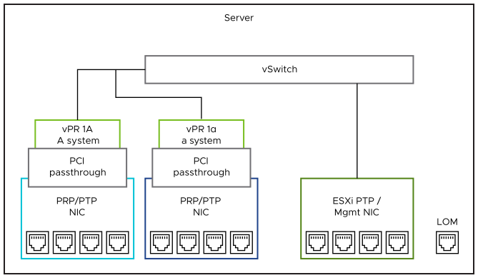
Optionally, a duplicate of an application can be implemented on each host (as shown in NIC SR-IOV with vPR 1A operating redundantly with vPR 1α). This can protect from NIC or internal VM failures (or possibly other redundant, dedicated components such as CPUs in the case of dual socket servers with properly separated allocation for each VM). But more significant events involving the entire host can likely still impair all resident workloads. Therefore, this approach is not considered a best practice for active-active appliance candidates.

Testing the failover of active-active applications must not be necessary, assuming each workload is tested individually when initially installed. This additionally assumes no single point of failure (physical or virtual) exists that can interrupt the duties of their critical functions.
Active-standby topology is suitable for workload types where a short failover duration (ranging from a few milliseconds to a few minutes) is acceptable. Example applications fitting this description are classified as vAC. For these, VMware has core capabilities that can be leveraged to achieve automated failover and resource management. With High Availability (HA) or Fault Tolerance (FT), which are VMware technologies (see Failover Techniques), a loss of supporting hardware, networking, or internal application heartbeat or activity (if supported through onboard VMware Tools) can trigger a new VM instance on adjacent healthy clustered hardware.
The testing procedures for HA and FT is covered in the following Hardware and Software Resiliency section.